V-Ray for Rhino
Surface Scattering Rollout
The Surface Scattering rollout is part of the Scatter parameters.
Last updated 20 May 2026
The Surface Scattering rollout is part of the Scatter parameters.
Parameters
This submenu is only available when the scattering mode is set to 2D - On Surfaces.
Mode – Specifies the surface scattering mode. See the Mode Example below.
Random Distribution – Scatters instances randomly on all mesh objects.
UV Grid – Uses UV mapping to scatter instances in regular patterns.

Example: Mode
This example shows the difference between Random Distribution and UV Grid modes. The scene for this example is set in inches.

Random Distribution

UV Grid
Random Distribution
Instances Count – Gives the total number of instances on all Host objects. Note that adding Area Modifiers or defining Slope Limitation will decrease this number. If the Per Area option is enabled, the scattering is defined by the density. See the Instances Count example below.
Per Area – When enabled, the number of instances is determined by the count combined with the size of the host's surface. The value specifies the length of the distribution area's side/edge. If the Count value is set to 1, this number determines the relative density of the instances. See the Per Area example below.
Pattern – Determines the density pattern. Select from a set of predefined distribution maps or use a custom texture.
None – No map is selected.
Custom Texture – Uses a custom texture.
Distorted Streaks High – Distorted streaks pattern with different densities.
Distorted Streaks Low – Distorted streaks pattern with different densities.
Groups High – Groups pattern with different densities.
Groups Low – Groups pattern with different densities.
Fractal Patches High – Fractal patches pattern with different densities.
Fractal Patches Low – Fractal patches pattern with different densities.
Straight Lines High – Straight lines pattern with different densities.
Straight Lines Low – Straight lines pattern with different densities.
Stretched Patches High – Stretched lines pattern with different densities.
Stretched Patches Low – Stretched lines pattern with different densities.
Density – Determines the approximate count of instances based on texture input. Black color in the texture discards all instances in the respective area. Areas colored with white receive the maximum number of instances. See the Density examples below.
Map Channel – Determines the UV channel. See the Density Map example below.

Example: Instances Count
This example shows the exact instances count on a host object.

Instances Count
= 1000

Instances Count
= 2500
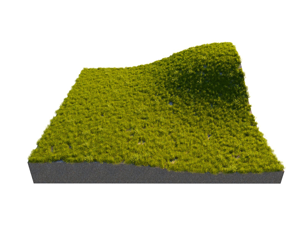
Instances Count
= 10000
Example: Per Area
The number of instances here is determined by the count combined with the size of the host's surface. The value specifies the length of the distribution area's side/edge.

Instanses Count
= 1000;
Per Area
= Off

Instanses Count
= 1000;
Per Area
= 1000

Instanses Count
= 1000;
Per Area
= 4000
Example: Density
The Density determines the approximate count of instances based on texture input. Black color in the texture discards all instances in the respective area.
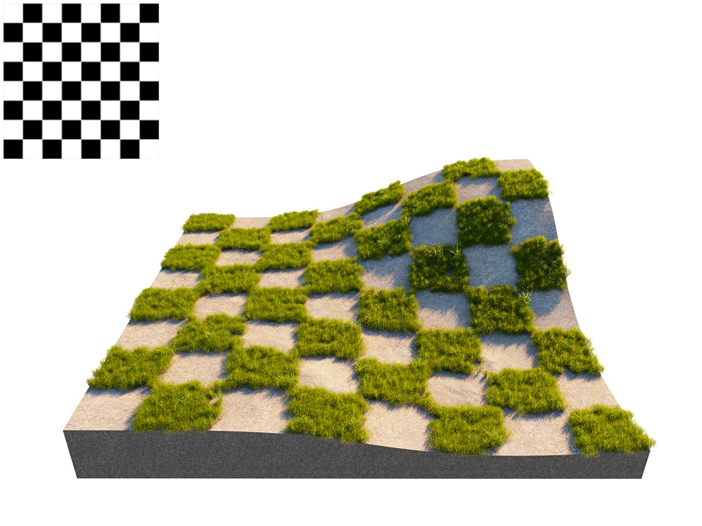
Instances Count
= 5000; Checker Map

Instances Count
= 5000; Noise Map
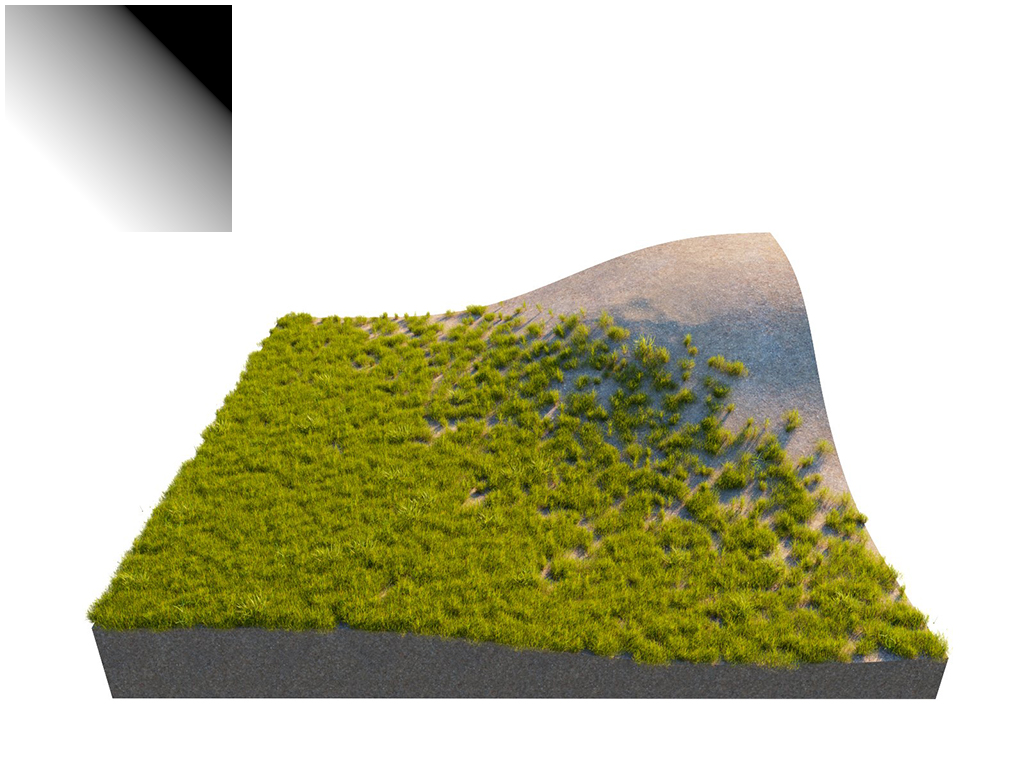
Instances Count
= 5000; Gradient Map
Example: Density Map
Using a Density map generates brand new instance distribution. The total number of instances (approximate to the 'Instance Count' value) is preserved and distributed on all surfaces that correspond to map values above 0 (parts of the map not being purely black). Instances are more likely to be generated in areas with higher Density map values than darker ones.
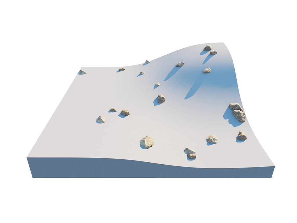
Off

Checker Map
UV Grid
Pattern – Determines a pattern to use for grid scattering. See the Pattern example below.
Grid – Rectangular grid.
Running Grid – Rectangular grid with every other row offset by half of the grid spacing.
Hexagonal Grid – Arranges the instances into hexagons.
Map Channel – Determines the UV channel.
Spacing – Scales the pattern in UV space. When Spacing is set to 1, the pattern occupies the whole space. When Spacing is set to 0.5, the pattern is repeated twice. See the Spacing example below.
Jitter – Determines what proportion of the instances are randomly placed. When Jitter is set to 0 all instances are placed according to the UV mapping. When Jitter is set to 1 all instances are randomly placed. See the Jitter example below.
Offset – Offsets the pattern by the given value (in percentages). Keep in mind that 0 and 1 Offset give the same result, as 1 moves the pattern by one whole repetition. See the Offset examples below.
Lock – When enabled the values of the V coordinate for Spacing, Jitter and Offset are locked to the U coordinate's values.

Example: Pattern
This example shows the different pattern types.
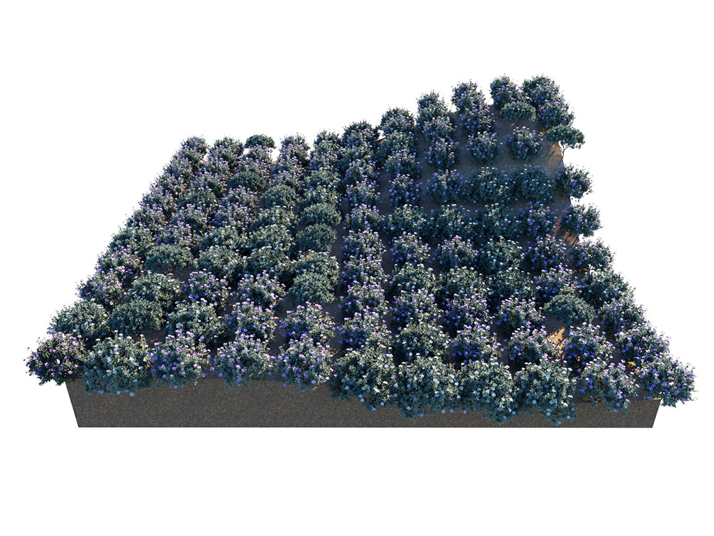
Spacing
= 0.1;
Pattern
= Grid

Spacing
= 0.1;
Pattern
= Running Grid

Spacing
= 0.1;
Pattern
= Hexagonal Grid
Example: Spacing
This example shows how the spacing parameter affects the distances between the Scatter guest objects.

Pattern
= Grid;
Spacing
= 0.1

Pattern
= Grid;
Spacing
= U 0.1; V 0.25

Pattern
= Grid;
Spacing
= 0.5
Example: Jitter
This is how Jitter affects the random placement of Scatter Guest objects. When set to 0, all instances are placed according to the UVW mapping. When set to 1, all instances are randomly placed.

Pattern
= Grid;
Jitter
= 0

Pattern
= Grid;
Jitter
= 1

Pattern
= Grid;
Jitter
= 2
Example: Offset by Single Axis - V
For this example, the Pattern is set to a rectangular Grid. Here, the offset is applied to the U axis only (the Lock V option is disabled).

Pattern
= Grid;
Offset
= U 0; V 0

Pattern
= Grid;
Offset
= U 0; V 0.5

Pattern
= Grid;
Offset
= U 0; V 1
Example: Offset Locked UV
For this example, the Pattern is set to a rectangular Grid. The offset is applied to both the U and V axes (the Lock V option is enabled).

Pattern
= Grid;
Offset
= U 0; V 0
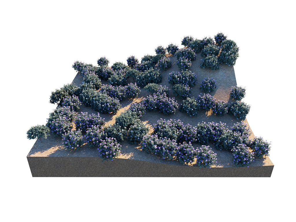
Pattern
= Grid;
Offset
= U 0.5; V 0.5

Pattern
= Grid;
Offset
= U 1; V 1
Edge Trimming
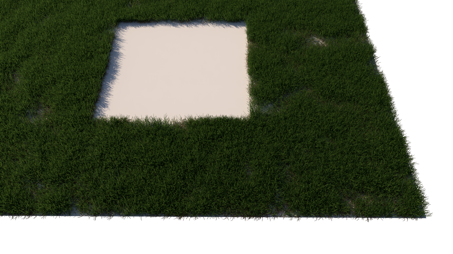
Edge Trimming – Trims elements of instances outside of the host boundaries. It affects both host objects and Area modifiers.
Edge trimming is used to trim scattered instances consisting of multiple mesh elements so that they stay within the boundaries of the host objects, taking into account the modifiers added to the Area Modifiers list. If an origin of any integral part of the instance (any sub-mesh element of the instanced model) falls outside of the area specified by the scatter, such part is not rendered. This is a simplification, but you can imagine the origin as a point on the host object from which an element is growing.
The typical use cases of Edge Trimming include:
- Grass lawns - in case of using large grass clumps, no individual grass blades will be growing outside of the defined area.
- Carpets - in case of using large clumps of strands, no individual strands will be placed outside of the carpet area.
- Pebbles, rocks, bark chippings, or any other objects which you need to distribute within some specific boundary and make sure no instances stick outside of that boundary (determined based on the mesh element origin precision).
In addition to making the scattering look more refined and natural, the edge trimming feature boosts performance by removing some of the instances you save from RAM and making parsing time shorter.

Example: Edge Trimming

Slope Limitation

– Enables the Slope Limitation parameters.
Slope Limitation –
Limits scattering only to 'slopes' at certain angles. The lower the angle range is set, the smaller the angle at which scattering stops. See the Slope Limitation Examples below.
Local – The Slope Limitation is measured according to the up vector of each individual scatter Host object.1
World – The Slope Limitation is measured according to the world Z-axis up vector for all Host objects.
Angle From – The lower limit of the range outside which instances get filtered out.
Angle To – The upper limit of the range outside which instances get filtered out.
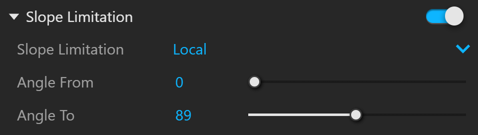
Example: Slope Limitation
This is an example of how the slope limitations work.

Slope Limitation
= Local;
Angle From
= 0;
Angle To
= 180

Slope Limitation
= Local;
Angle From
= 0;
Angle To
= 45

Slope Limitation
= Local;
Angle From
= 15;
Angle To
= 45

(Rotated)
Slope Limitation
= Local;
Angle From
= 15;
Angle To
= 45

(Rotated)
Slope Limitation
= World;
Angle From
= 15;
Angle To
= 45
Example: Multiple Hosts Slope Limitation
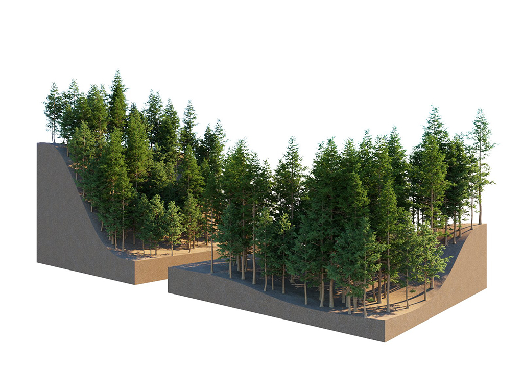
This example shows how a group of multiple guest objects can be distributed over several more than one host object.

Altitude Limitation
Еnables instances limitation in the given altitude range.
Altitude Limit Mode – Defines the range of altitude units in World or Local mode.
Local – The altitude is measured relative to the object’s origin.1
World – The altitude is measured relative to the world’s origin.
Min Altitude (cm) - Determines the minimum altitude. Objects below this threshold are not rendered.
Max Altitude (cm) - Determines the maximum altitude. Objects above this threshold are not rendered.
Curve Editor – Remaps the Min/Max altitudes.
Interpolation – Determines the curve interpolation.
Linear – Values are linearly interpolated.
Cubic – Values are interpolated using a smooth cubic curve.
See the context menus here.


Clustering
Mode – Determines the clustering method.
Procedural Noise – A way to procedurally cluster the instances.
Color Map – Uses a texture as input for the clustering mode. For each Guest object, a Cluster color can be defined. The Cluster colors need to be present in the texture in order for this feature to work. Guests are scattered in the areas with the same color in the texture. See the Color Map example below.
Cluster Painting – Uses brush strokes to paint clusters in separate layers.
Texture Placement – Determines how the procedurally generated map is positioned.
XY - The texture is projected from the top.
UV - The texture is positioned based on the host’s UV texture coordinates.
Seed – Applies different variations of the pattern based on the Seed number.
Example: Seed


Size – Specifies the average size of the clusters on the X and Y axes. The larger the Size value, the larger the Clusters will be. Available when XY is selected.
Example: Size
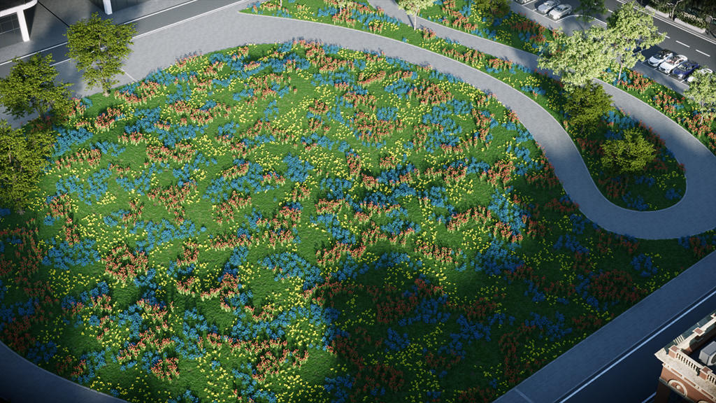


Scale – Scales the clustering pattern along the UV coordinates. Available when UV is selected
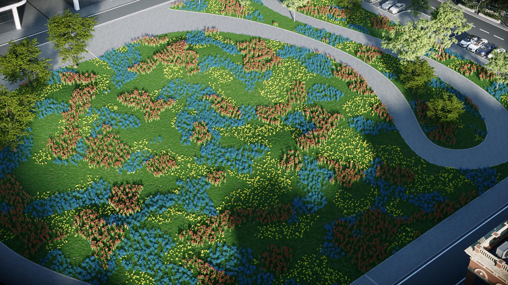
Rotation – Rotates the clusters around a center. For the UV mapping, it is 0,0 and for XY mapping it is the geometry center of a target object or the common center for all the target objects in the list.
Example: Rotation


Offset X/Y – Offset along X axis or Y axis. The offset direction depends on the rotation of the clusters. Available when XY is selected.
Example: Offset X/Y
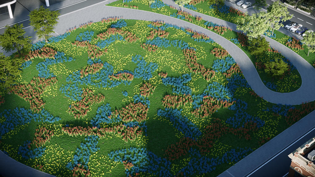
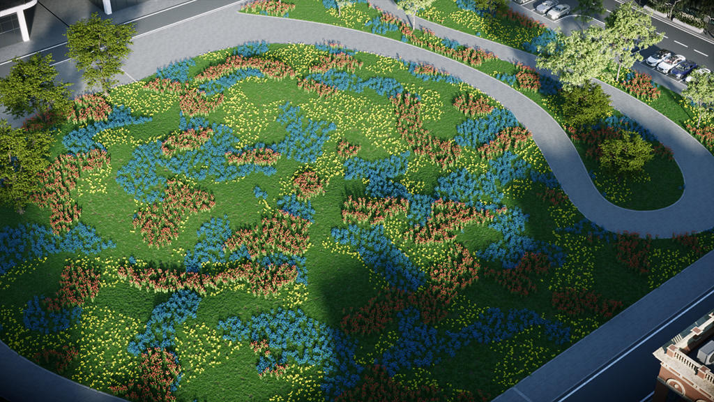
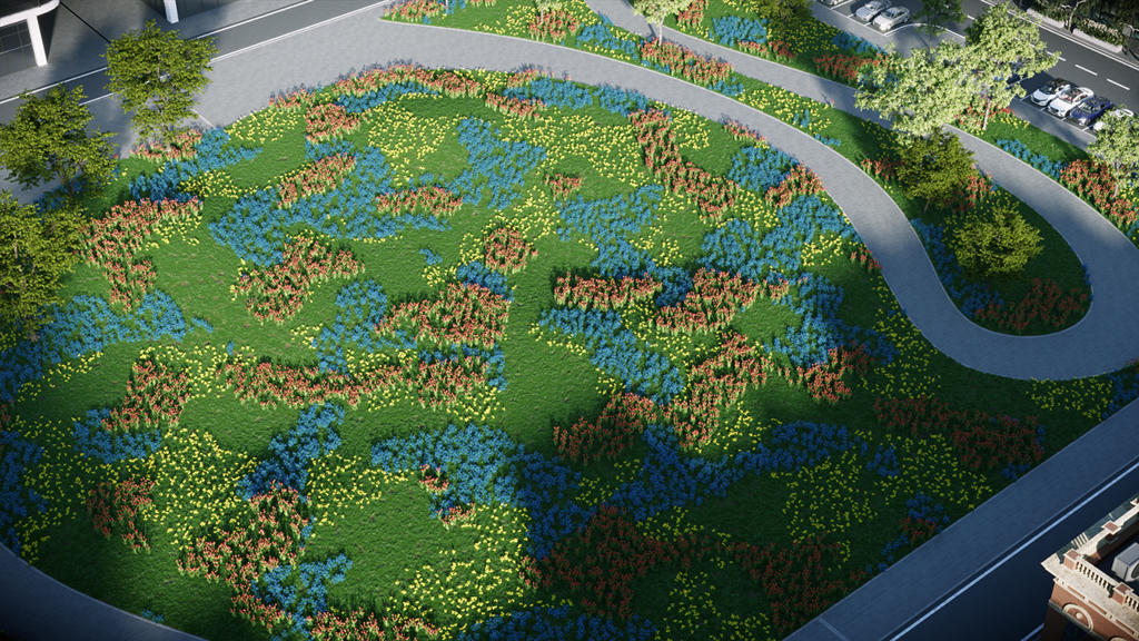
Offset U/V – Offset along U axis or V axis. The offset direction depends on the rotation of the clusters. Available when UV is selected.
Roughness % – Lower values produce rounded clusters, while higher values produce more jagged shapes.
Example: Roughness %


Blend % – Blurs the edges between clusters.
Example: Blend %


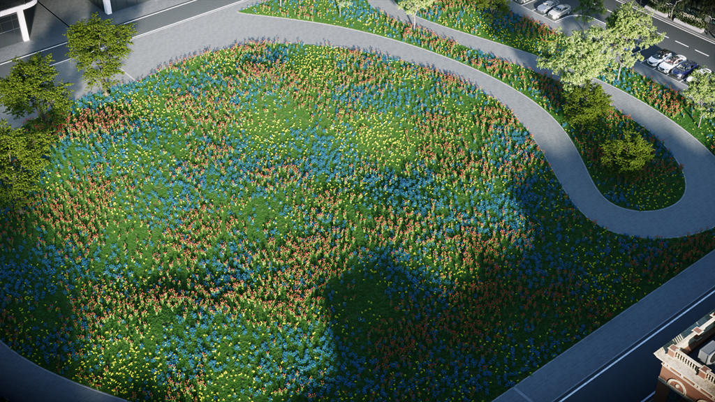
Diversity % – Allows a small number of objects from the Clusters to appear inside a given Cluster. Smaller values mean that fewer instances are taken from the other clusters. Bigger values mix instances from other clusters.
Example: Diversity %
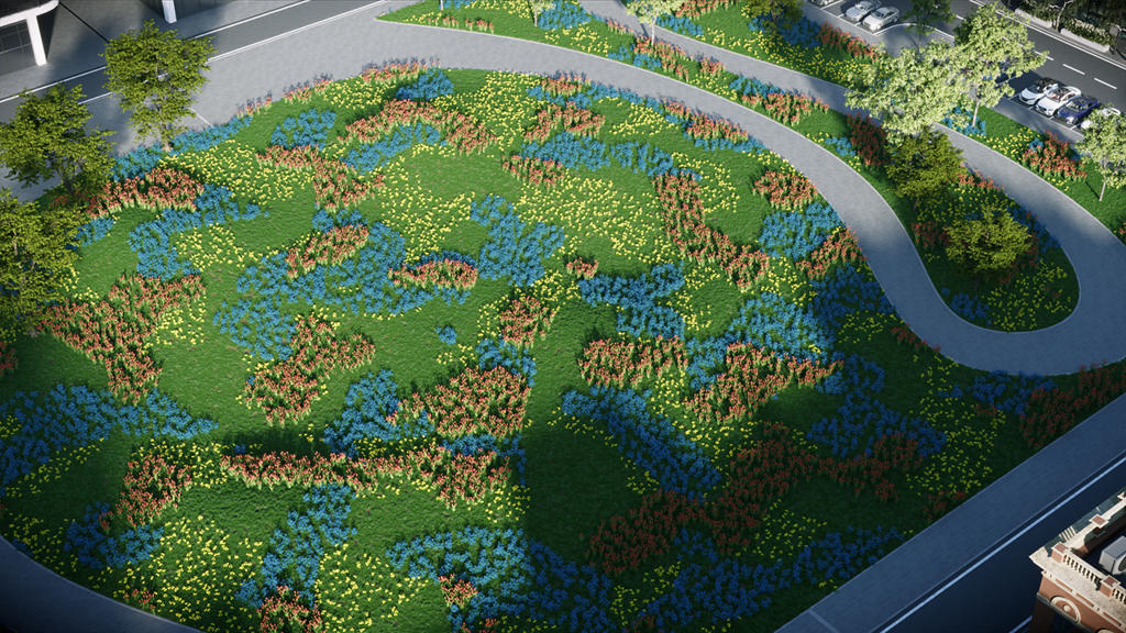
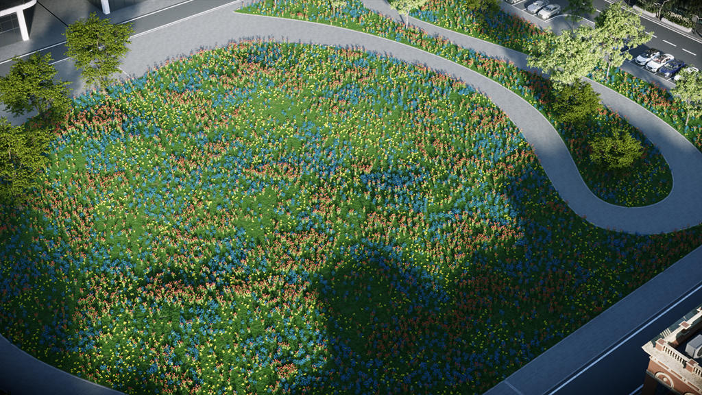


Procedural Noise Mode

Color Map Mode
Example: Color Map Mode
This example shows the map used and the rendered result.

Cluster Painting
The Cluster Painting option in the Scatter Clustering dropdown adds clusters as brush strokes on separate layers. It includes a base layer containing the main elements (for example, grass applied across the entire plane) and separate additional layers that hold various elements used to create clusters. For instance, one layer may include tulips that we want to add to specific areas of the plane, while another layer could contain roses, and so on.

– Add Layers – Add more Cluster Painting layers.

– Add Guests – Add guest objects to the specific layer.

– Paint Strokes – Paint strokes to the specific layer.
Rad – Adjust the radius of the guest objects.
Mode - Use Add/Sub to add or subtract guest objects from the cluster.

– Layer Options – Add strokes from a selection or delete the layer.

Workflow
- Enable Clustering and select Cluster Painting mode in a scene that contains Scatter with added guests.
- Add guests to the Base layer by clicking Add Guests. Select one or more guests from the dropdown list of available Scatter guests.
- Create Cluster layers by clicking Add Layer. Add guests to each layer.
- Click Paint Strokes to draw strokes in model space for each layer. Draw strokes using either Click–Click or Click–Drag. Press Space or Enter to confirm and deactivate the tool after finishing the stroke.
- View strokes listed under the layer to which they belong.
- After creating the Base layer and Cluster layers and adding strokes, adjust the Radius (Rad) for each stroke. Use Add/Sub for each stroke to control whether the stroke adds guests to or removes guests from the cluster.
www.youtube.com
Notes
- There is no Local space in Rhino. As a result, this mode uses the World space Up vector. This option is exposed in the UI to ensure interoperability with other V-Ray products where a distinction between local and world positions is valid.