Chaos Vantage
Chaos Scatter
This page provides information about Chaos Scatter in Chaos Vantage.
Last updated 20 March 2026
This page provides information about Chaos Scatter in Chaos Vantage.
Overview
Chaos Scatter is a powerful instancing and distribution tool that allows you to easily populate scenes with selected objects. This is especially useful for outdoor scenes that need to be filled with greenery, rocks, grass, etc.

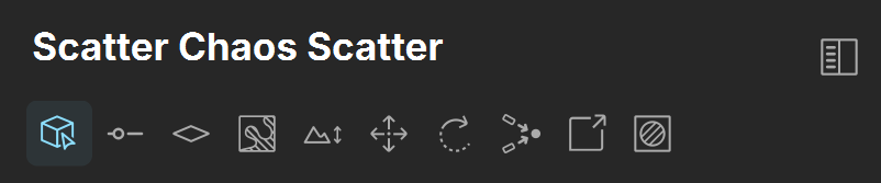
Chaos Scatter parameters are grouped into several tabs (see the following table) in the Objects tab. They can be separated into their own column via the Splitter () button.
Button | Description |
|---|
Button | Description |
|---|---|
Objects tab – Contains settings for picking objects to scatter as well as objects onto which you scatter other objects. | |
Scattering tab – Contains general settings for scattering objects. | |
Spline scattering tab – Contains settings for scattering objects on splines. | |
Surface scattering tab – Contains settings for scattering objects on surfaces. | |
Clusters tab – Contains settings for combining patches of the same scattered instance. | |
Slope and altitude limits tab – Contains settings for limiting the scattering only to slopes at certain angles. | |
Volume scattering tab – Contains settings for scattering objects within the bounding box of objects. | |
Translate tab – Contains settings for position transformations of the scattered objects. | |
Rotation tab – Contains settings for rotation transformations of the scattered objects. | |
Look at tab – Contains settings for managing a look at target for the scattered objects. | |
Scale tab – Contains settings for scaling transformations of the scattered objects. | |
Areas tab – Contains settings for controlling the areas of the scattering effect. |
UI Path
||Top toolbar|| > Create new Geometry object > Chaos Scatter
||Right side panel|| > Objects tab > Create new Chaos Scatter object
Objects
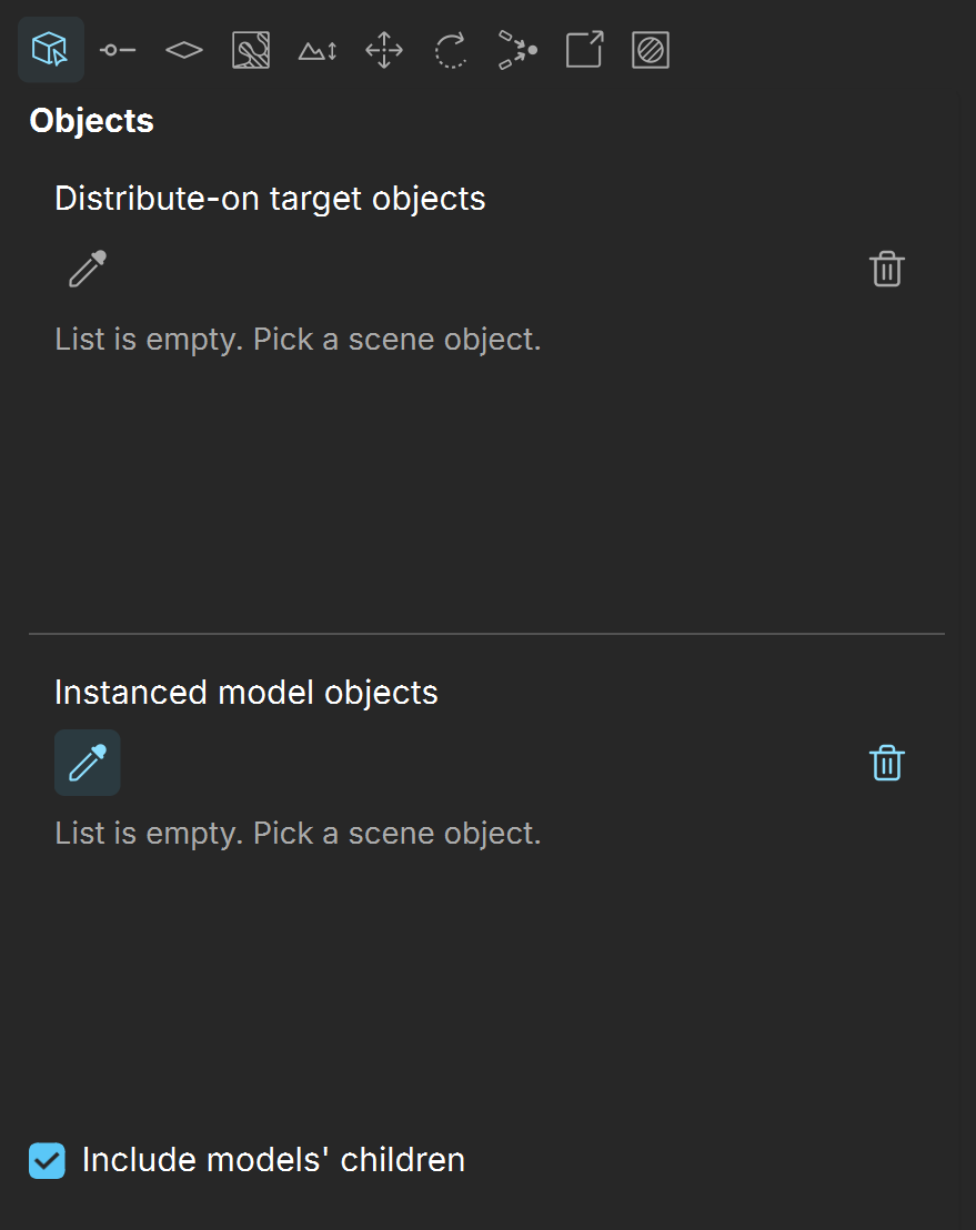
Distribute-on target objects – Specifies the object(s), on which the instances will be scattered.
Instanced model objects – Specifies the objects which will be scattered on the distribute on-target object(s).
Include models' children – When enabled, Vantage scatters not only the parent instanced model but its children geometry as well.
Scattering settings
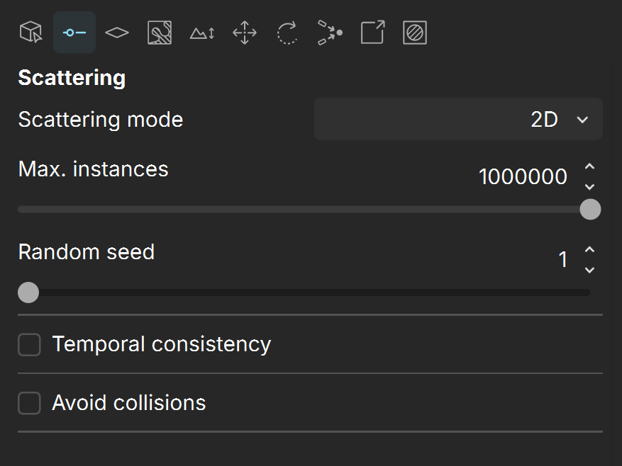
Scattering mode – Specifies the scattering mode:
1D – Scattering mode where objects are scattered along splines. Open or closed splines can be used for this. Note that this mode is supported only for imported vrscenes.
2D – Scattering mode where objects are scattered on surfaces. It doesn't matter if the surface is horizontal, vertical, or if it is part of a complex 3D object.
3D – Scattering mode where objects are scattered inside the object's bounding box. Keep in mind that bounding boxes are cube-shaped, therefore using this mode on a round object scatters instances in a cube around it. This mode is useful when scattering dust particles inside a room, fish in an aquarium, books on a bookshelf and similar.
Max. instances – Limits the maximum number of instances. Note that this option does not determine how many instances are created. Instead it serves as a measure to avoid scattering too many instances and causing a crash.
Random seed – Determines the random distribution used. Changing this value causes random permutations of the scattered object(s). See the Random Seed example below.
Temporal consistency – When enabled, instances are scattered in the selected Rest-pose frame and stick to the surface, even if it gets deformed in other frames. Otherwise, instances get scattered in each frame separately and that might cause anomalies.
Rest-pose frame – Determines the initial frame, where the instances are scattered for all following frames.
Avoid collisions – When enabled, instances that would collide with each other get discarded. This results in no overlaps between instances. Note that enabling this option might lower the number of instances. See the Avoid Collisions example below.
Spacing [%] – Controls the size of the bounding boxes used to detect collisions. Smaller values result in denser instances with some collision, higher values result in larger distances between instances. Values above 100% mean that the distance between objects is larger than their bounding boxes. See the Avoid Collisions example below.
Spline scattering
The following parameters are available when Scattering mode is 1D.
Spacing – Determines the spacing between instances in world units. See the Spline Spacing example below.
Jitter – Randomly jitters instances along the spline. Spacing is applied to both sides of each instance, except the instances at the end of the spline. The Jitter value is divided between those two Spacings. In order to allow instances to jitter in all their Spacing distance, the Jitter needs to be set to 200%. See the Spline Jitter example below.
Offset – Determines what percentage of the Spacing the instances are offset in one direction of the spline. When set to 100%, all instances replace the one after them, as the offset is equal to the whole value of the Spacing. See the Spline Offset example below.
Follow amount – Determines how scattered instances are oriented along the spline. Assigning a value of 100%, makes instances follow the spline and are oriented along the local tangent direction. See the Spline Follow Amount example below.

Surface scattering
The following parameters are available when Scattering mode is 2D.
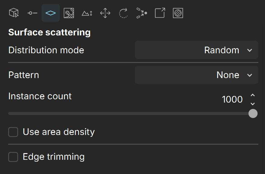
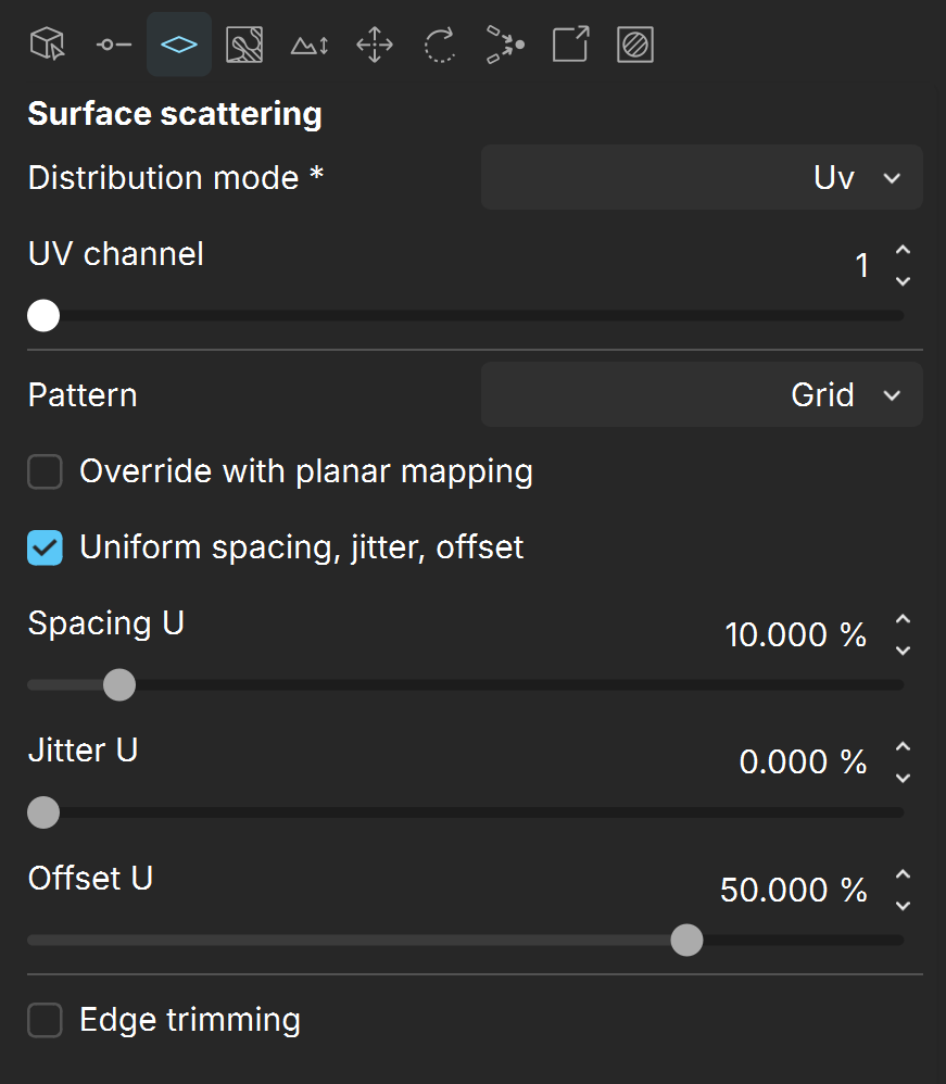
Distribution mode – Specifies the scattering method:
Random – Scatters instances randomly on all mesh distribution objects. It is enabled by default.
UV – Uses UVW mapping to scatter instances in regular patterns.
Pattern – Selects from predefined distribution maps or chooses a custom map.
None – No map is selected.
Custom map – Uses a custom map from the. vrscene. Cannot be edited.
Distorted streaks high/low – Distorted streaks pattern with different densities.
Groups high/low – Groups pattern with different densities.
Fractal patches high/low – Fractal patches pattern with different densities.
Straight lines high/low – Straight lines pattern with different densities.
Stretched patches high/low – Stretched lines pattern with different densities.
Instance count – Determines the exact number of instances to scatter. If the Use area density option is enabled, the scattering is defined by the density. See the Instance Count example below.
Use area density – When enabled, the Instance count amount is multiplied by the specified Square area.
Square area – Specifies a multiplier for the Instance count when Use area density is enabled. See the Square Area example below.
Edge trimming – Trims elements of instances outside of distribute-on objects.
The following parameters are available when Scattering mode is 2D and Distribution mode is UV.
UV channel – Determines the UV channel of the distribute-on target that will be used for the Pattern texture.
Pattern – Determines a pattern to use for scattering. See the Surface Scattering Pattern example below.
Grid – Rectangular grid.
Running grid – Rectangular grid with every other row offset by half of the grid spacing.
Hexagonal grid – Arranges instances into hexagons.
Override with planar mapping – When enabled, a simple planar UVW mapping is created and used instead of the pre-existing UVW channels.
Projection axis – Specifies the axis for the simple planar mapping.
Uniform spacing, jitter, offset – When enabled, the values of the V coordinate for Spacing, Jitter and Offset are locked to the U coordinate's values.
Spacing U / V– Scales the pattern in UV space. When Spacing is set to 100%, the pattern occupies the whole space. When Spacing is set to 50%, the pattern is repeated twice. See the Surface Scattering Spacing example below.
Jitter U / V – Determines what percentage of the instances are randomly placed. When Jitter is set to 0, all instances are placed according to the UVW mapping. When Jitter is set to 100, all instances are randomly placed.
Offset U / V – Offsets the pattern by the given value (in percentages). Keep in mind that 0% and 100% Offset gives the same result, as 100% moves the pattern by one whole repetition.
Edge trimming – Trims elements of instances outside of distribute-on objects.
Volume scattering
The following parameters are available when Scattering mode is 3D.
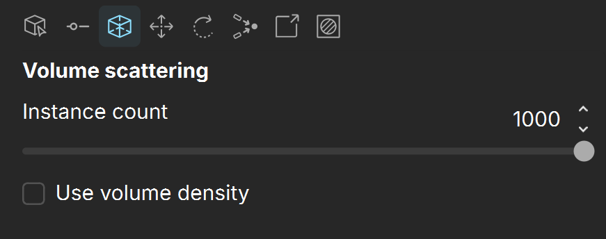
Instance count – Determines the exact number of instances to scatter. If the Use volume density option is enabled, the scattering is defined by the density (Cube volume).
Use volume density – When enabled, the scattering is defined by the density (Cube vol.)
Cube vol. – Multiplies the Instance count value when Use volume density is enabled.
Clusters
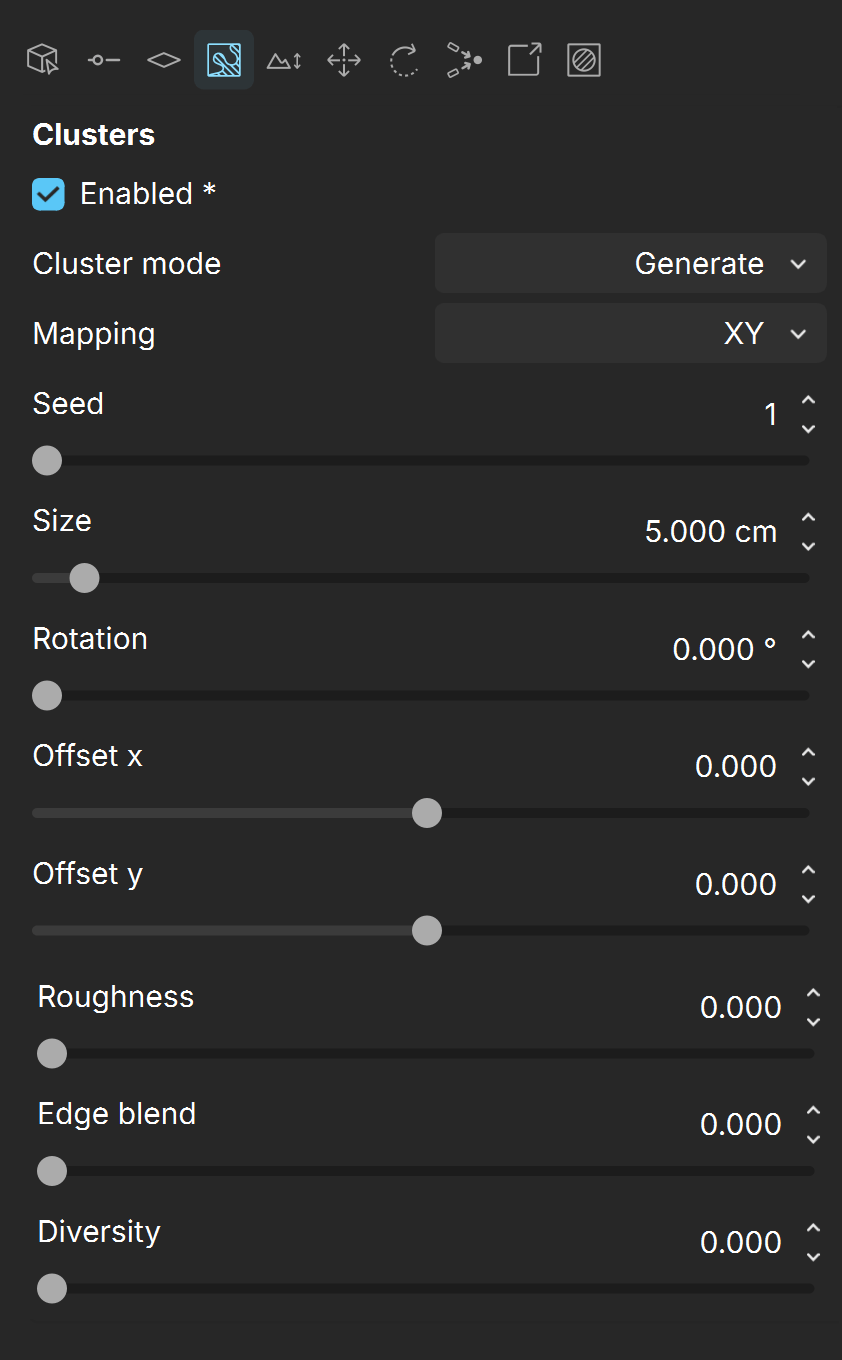
Enabled – Allows the combination of patches of the same instance, thus achieving a more natural look.
Cluster mode – Specifies the clustering mode:
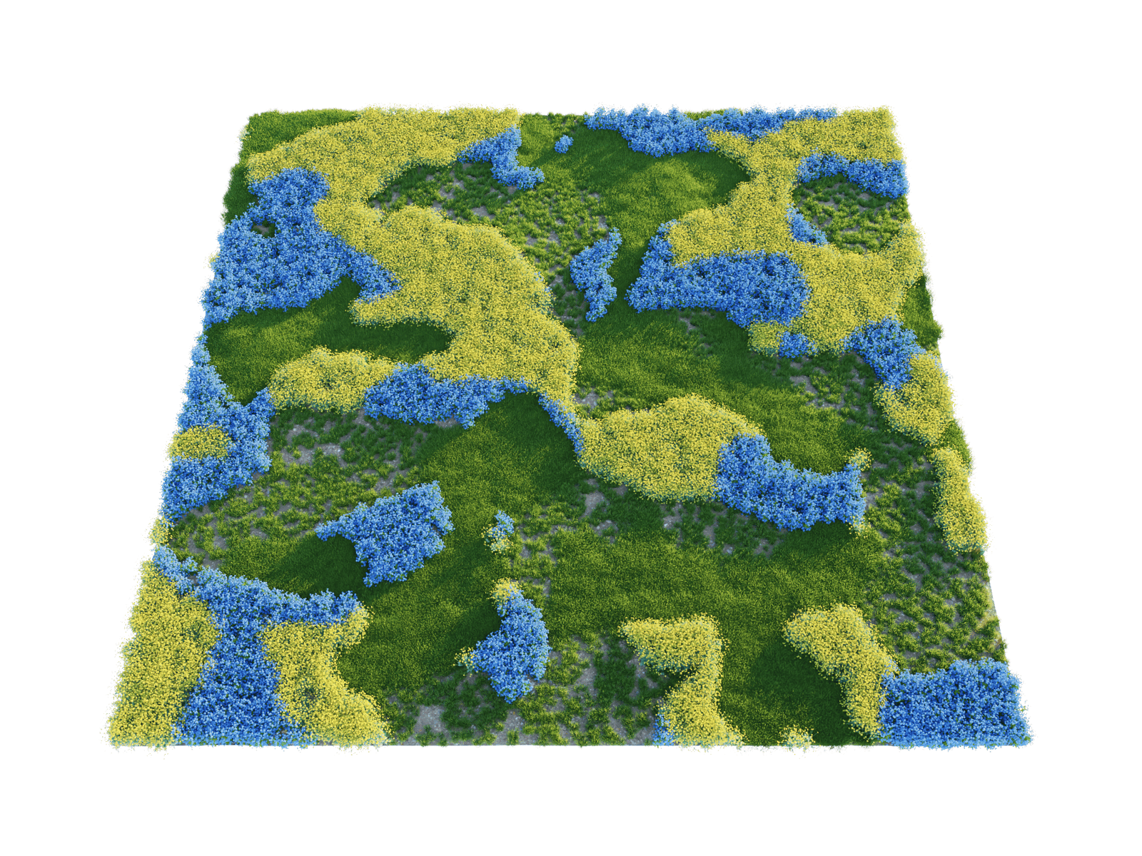
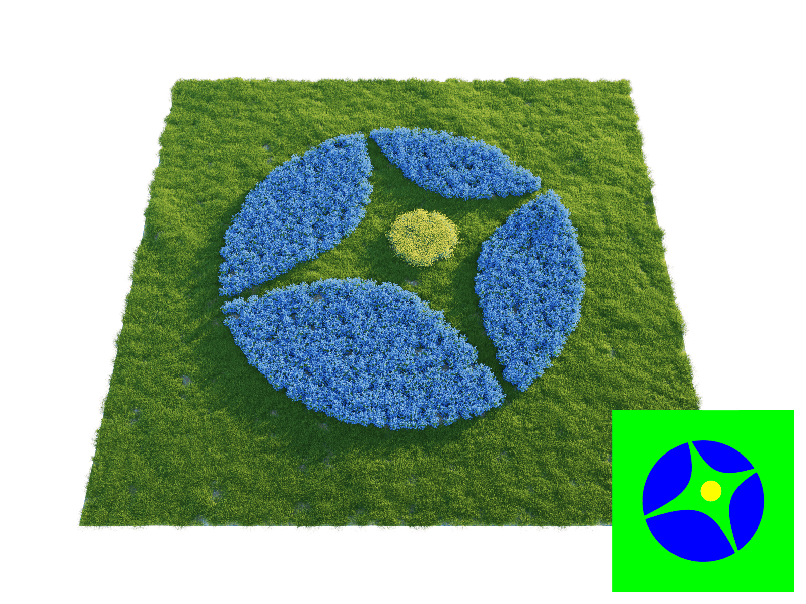
Generate – Clusters are created out of the list of objects. The distribution of the clusters is guided by a procedural noise map.
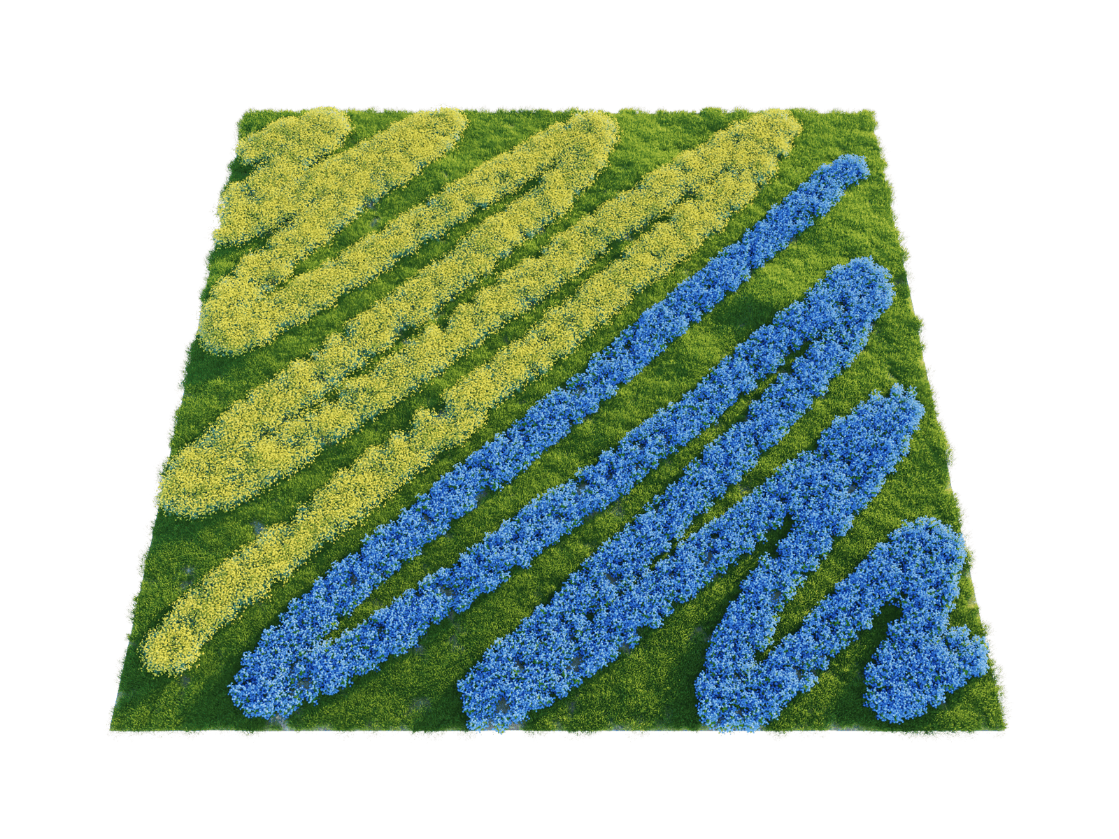
Color Map – Takes a bitmap as input. For each object, an Instance color can be defined, and then the instances are scattered in the areas with a close-matching (not identical) color in the bitmap. This mode works for imported .vrscenes only.
Clusters by layers – This mode uses layers. The order of the layers defines which of the objects are going to be visible. This mode works for imported .vrscenes only.
Mapping – Chooses between system unit distribution or UV mapping coordinates.
UV Channel – Specifies the source UV channel for the mapping coordinates. Available when UV is selected.
Seed – Applies different variations of the patternScale – Scales the clustering pattern along the UV coordinates. Available when UV is selected.
Click here to see the Seed example.
Size – Specifies the average size of the clusters on the X and Y axes. The larger the Size value, the larger the Clusters will be. Available when XY is selected.
Click here to see the Size example.
Rotation – Rotates the clusters around a center. For the UV mapping, it is 0,0 and for XY mapping it is the geometry center of a target object or the common center for all the target objects in the list.
Click here to see the Rotation example.
Offset x / y – Offset along X axis or Y axis. The offset direction depends on the rotation of the clusters. Available when XY is selected.
Offset u / v – Offset along U axis or V axis. The offset direction depends on the rotation of the clusters. Available when UV is selected.
Click here to see the Offset example.
Roughness – Lower values produce rounded clusters, while higher values produce more jagged edges.
Click here to see the Roughness example.
Edge blend – Blurs the edges between different clusters.
Click here to see the Edge Blend example.
Diversity – Allows a small number of objects from the Clusters to appear inside a given Cluster. Smaller values mean that fewer instances are taken from the other clusters. Bigger values mix instances from other clusters.
Click here to see the Diversity example.
Clusters Modes
The following example demonstrates the three cluster modes in Vantage. In the Generate mode, a procedural map is used to guide the clusters of grass, blue forget-me-not flowersvand yellow marigold flowers. In the Color Map mode, a vrscene is imported from 3ds Max and the same vegetation is distributed in clusters through a bitmap. In the Clusters by layer mode, again a vrscene is imported from 3ds Max where the vegetation is distributed in layers.
Generate Mode
Color Map Mode
Clusters by layers Mode
Slope and altitude limits
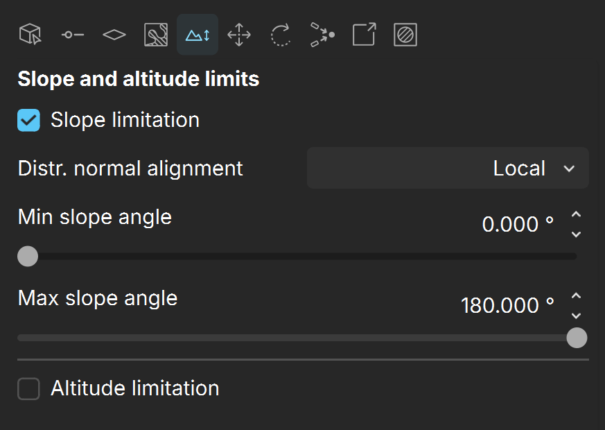
The Slope and altitude limits tab is available only for 2D Scattering mode.
Slope limitation – Limits scattering only to 'slopes' at certain angles. It can be used to create realistic spread of trees on curved surfaces, for instance. The lower the Min and Max slope angles are, the smaller the angle at which scattering stops. See the Slope Limitation example below.
Distr. normal alignment – Specifies between the Local up or the World up vector and the surface normal at which the scattered objects are distributed.
Local – When enabled, the slope limitation is measured according to the up vector of each individual Distribute-on target object.
World – When enabled, the slope limitation is measured according to the world Z-axis up vector for all Distribute-on target objects in the scene.
Min / Max slope angle – Defines a range of angles to which the scattering is limited. Instances outside of this range get filtered out. See the Slope Limitation example below.
Altitude limitation – Еnables instances limitation in the given altitude range.
Limit mode – Defines the range of altitude units in World or Position Independent mode.
World – The altitude of the surface points on each individual distribute-on object is evaluated in world space (after all transforms).
Position Independent – The altitude of the surface points on each individual distribute-on object is evaluated relative to the object center while the object rotation and scale still affect the altitude.
From – Minimum value of the altitude limitation.
To – Maximum value of the altitude limitation.
Translate
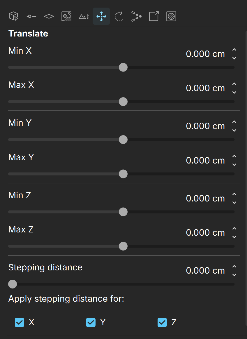
Min X /Max X – Moves the instances from the given minimum distance to the given maximum distance on the X axis.
Min Y /Max Y – Moves the instances from the given minimum distance to the given maximum distance on the Y axis.
Min Z /Max Z – Moves the instances from the given minimum distance to the given maximum distance on the Z axis.
Stepping distance – Determines a distinct distance between all instances in the enabled axes. If the values is left at zero, instances are translated continuously.
Apply stepping distance for X / Y / Z – Enables X / Y / Z axes when a value for the Stepping distance is specified.
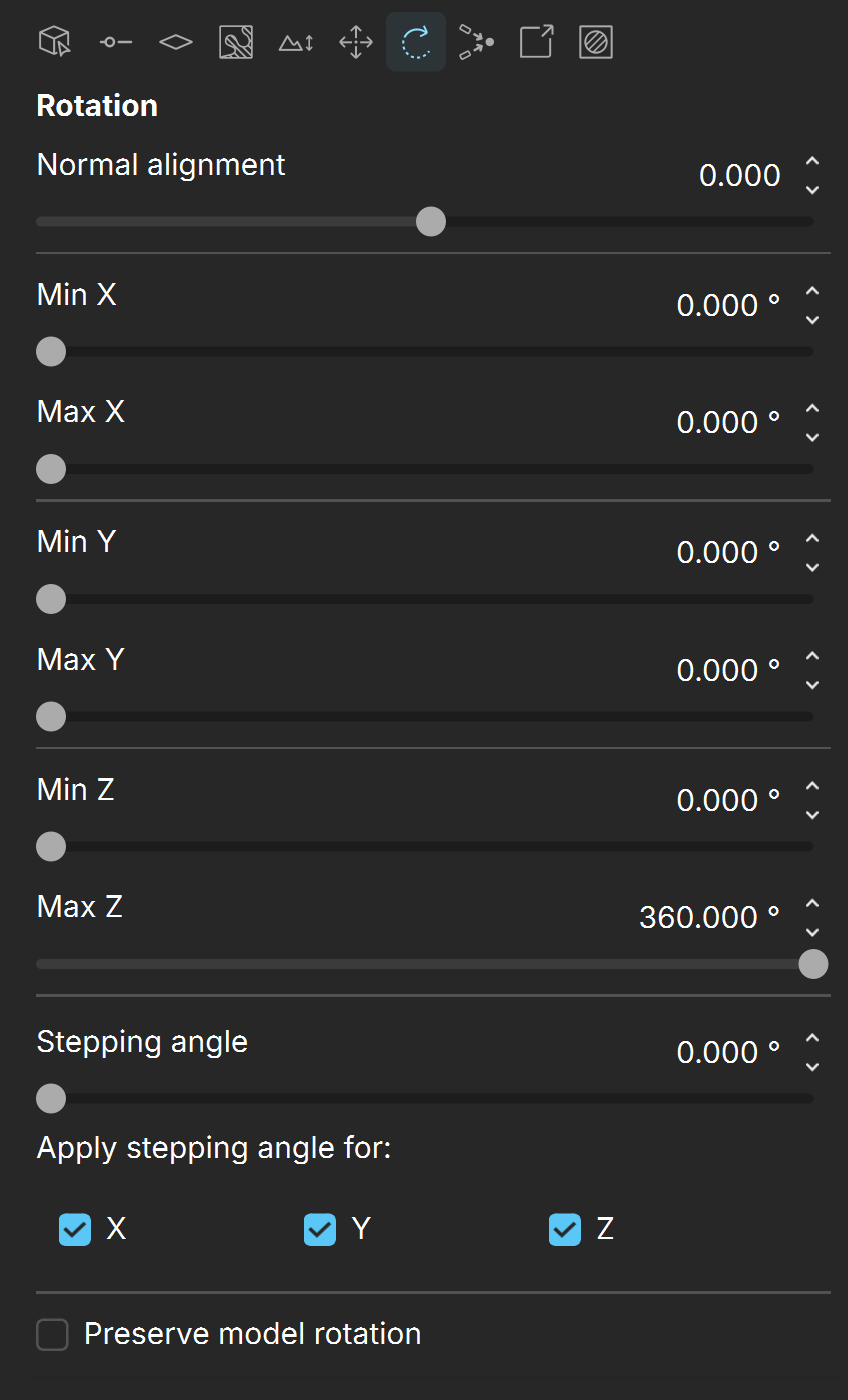
Rotation
Normal alignment – When a value different than 0 is entered, the instances are aligned according to the world Z axis. This is useful when the Distribute-on target object is curved and the scattered objects need to remain vertical, not follow the curve of the surface. Positive values mean that the instances are aligned to the +Z axis (vertical up) and negative values mean that the instances are aligned to the -Z axis (vertical down).
Min X / Max X – Rotates the instances from the given minimum degrees up to the given maximum degrees continuously on the X axis. See the Rotation example below.
Min Y / Max Y – Rotates the instances from the given minimum degrees up to the given maximum degrees continuously on the Y axis. See the Rotation example below.
Min Z / Max Z – Rotates the instances from the given minimum degrees up to the given maximum degrees continuously on the Z axis. See the Rotation example below.
Stepping angle – Determines a fixed degree by which all instances rotate for the enabled axes. See the Stepping Angle example below.
Apply stepping angle for X / Y / Z – Enables X / Y / Z axes when a value for the Stepping angle is specified. See the Stepping Angle example below.
Preserved model rotation – When enabled, preserves the initial rotation of the selected instanced model.
Look at
Enabled – When on, instances in a range get turned towards a specified direction.
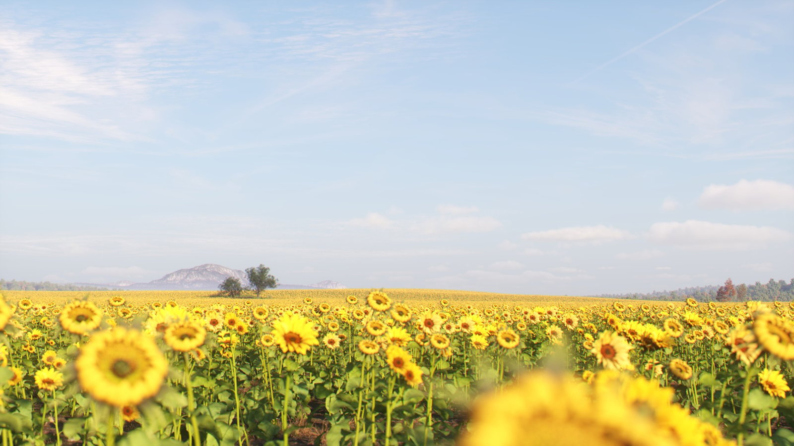
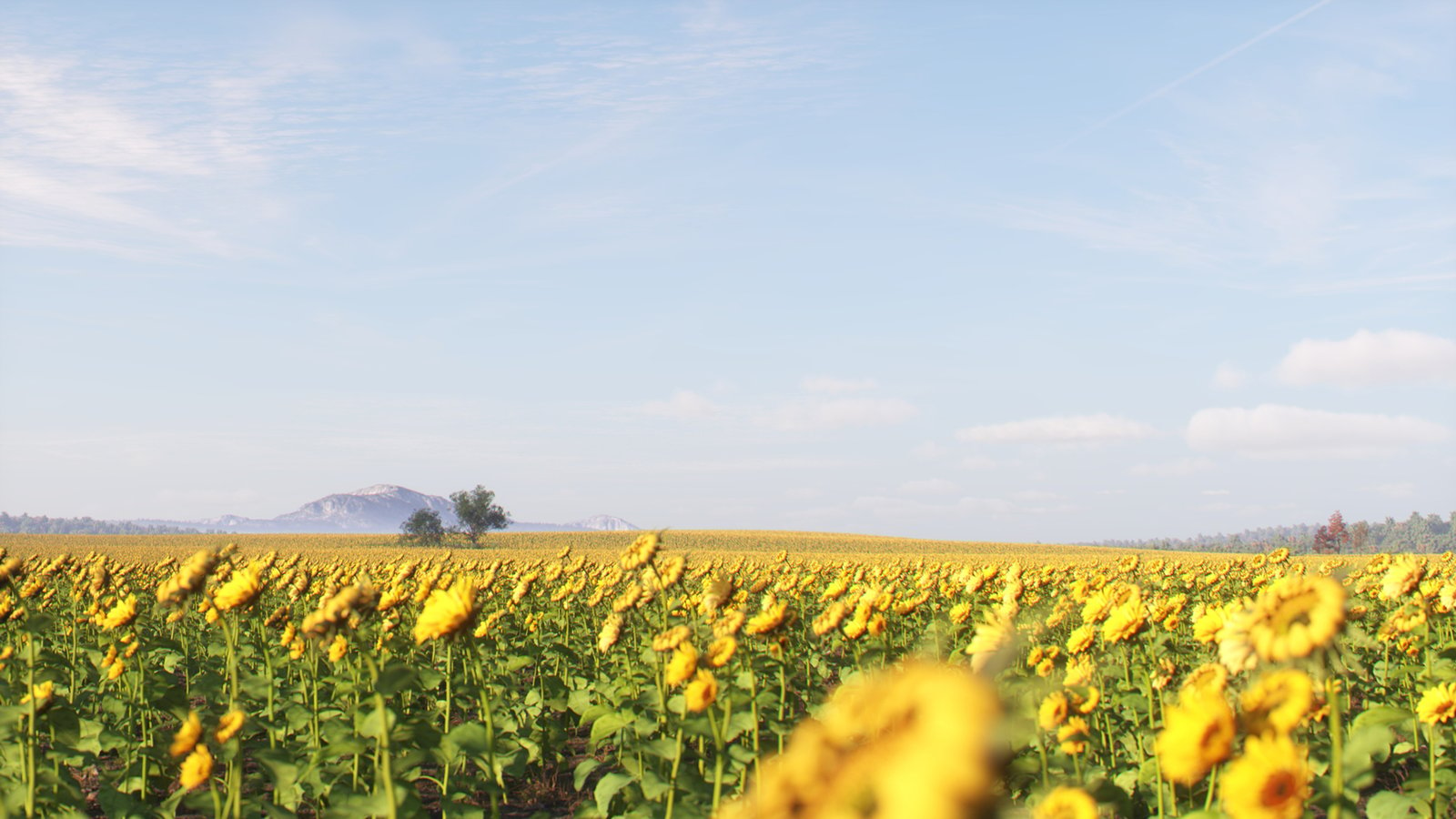
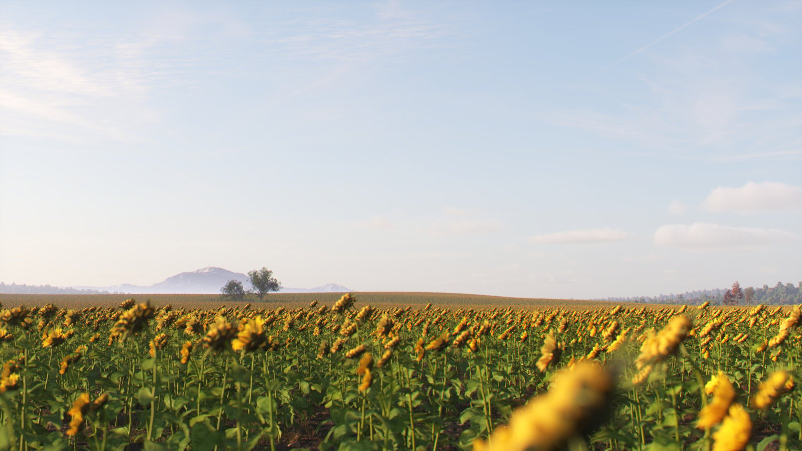
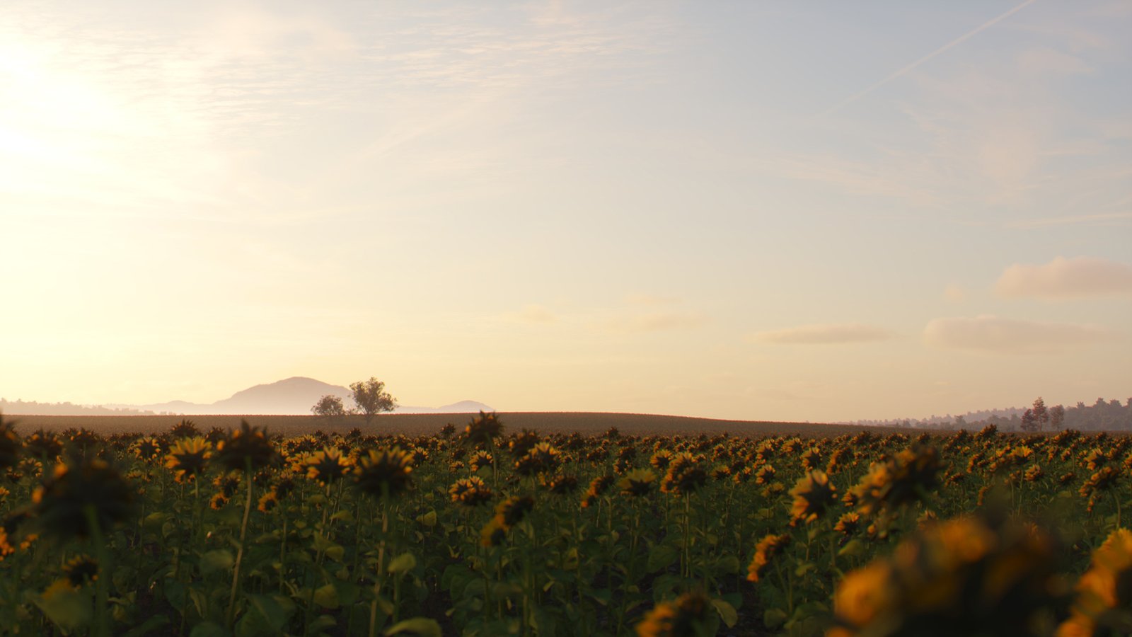
Target object – Picks an object according to which the direction is calculated. When a geometry object is picked, each instance gets oriented towards the center of the object’s bounding box. When a camera object is picked, each instance gets oriented towards the camera. See the Target Object example below.
Orientation axis – Selects which of the model object's axes gets turned towards the direction.
Reverse – When enabled, the reverse of the selected axis gets turned towards the direction.
Horizontal – When enabled, the selected look-at axis gets turned only within the plane which is perpendicular to the normal. See the Target Object example below.
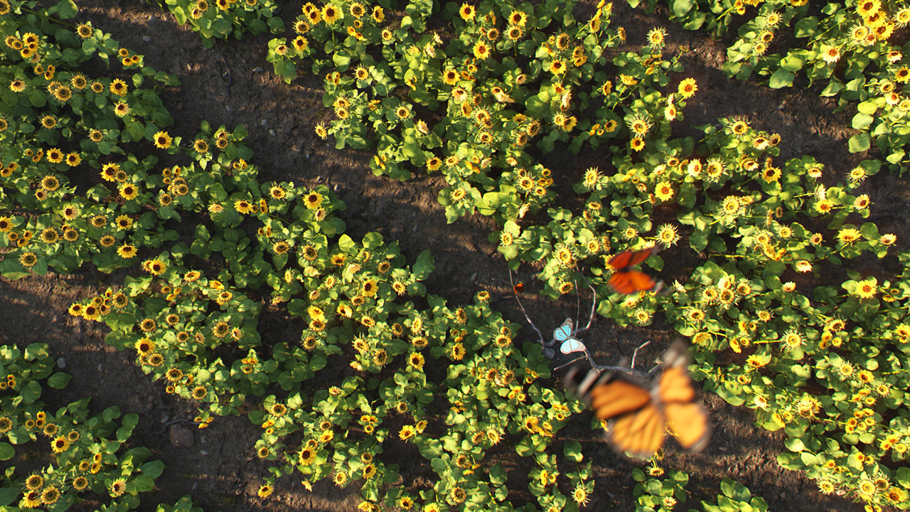
Falloff distance – Specifies the range in which instances get affected by the look-at specifications. When non-zero, only the in-range instances get affected; otherwise, all the instances get affected. There is no effect when a sun object is picked. See the Falloff Distance example below.

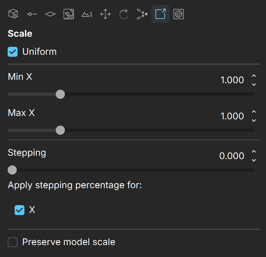
Scale
Uniform – When enabled, all instances in all axes are scaled according to the values of the X axis. See the Scale example below.
Min X / Max X – Scales the instances from the given minimum value to the given maximum value continuously. See the Scale example below.
Min Y / Max Y – Scales the instances from the given minimum value to the given maximum value continuously. When Uniform is enabled, the X axis values are applied to the whole distribute-on target object. See the Scale example below.
Min Z / Max Z – Scales the instances from the given minimum value to the given maximum value continuously. When Uniform is enabled, the X axis values are applied to the whole distribute-on target object. See the Scale example below.
Stepping – Determines a percentage of scaling to be applied to all instances. Otherwise, scaling is continuous. See the Scale example below.
Apply stepping percentage for X / Y / Z – Enables X / Y / Z axes when a value for the Stepping is specified. See the Scale example below.
Preserved model scale – When enabled, preserves the initial scale of the selected instanced model. See the Scale example below.
Areas
Include – Scatters the models only inside the bounding boxes of the objects included in this list. The objects cannot be the same as the distribute-on target objects.
Exclude – Scatters the models everywhere on the distribute-on target objects, except in the areas where the objects from the list are located. The objects cannot be the same as the distribute-on target objects. This option is useful, for instance, for removing instances of grass/trees from areas where a house needs to be located.
Near / Far – Determines the falloff distance from the selected object to the selected axis plane (Projection). If the selected object is from the Include list, instances within the falloff distance are included. If the selected object is from the Exclude list, instances within the falloff distance are excluded.
Scale – Scale factor further affecting the instances between the near and far falloff.
Density – Density factor further affecting the instances between the near and far falloff.
Projection – Specifies the axis on which to project the include/Exclude objects to the specified Distribute-on target objects.

Examples
Example: Random seed
This example shows the random Scatter seed distribution.
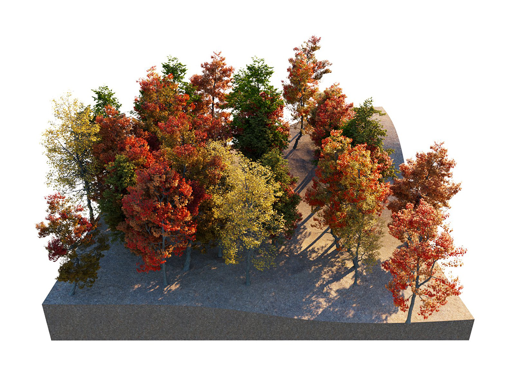
Random seed = 1

Random seed = 2
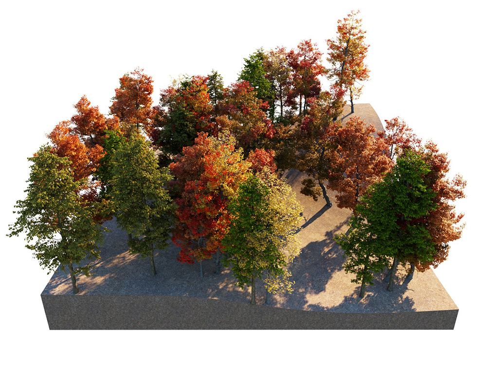
Random seed = 3
Example: Avoid collisions
This example shows how the Avoid collisions function works. Higher values result in larger distance between instances.
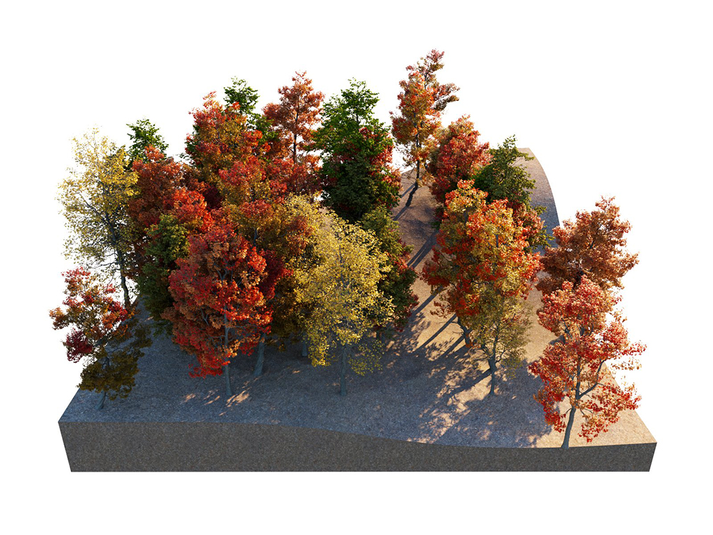
Avoid collisions = Off
Avoid collisions = Off
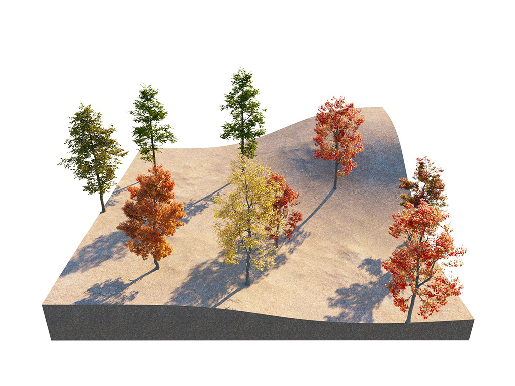
Avoid collisions = On; Spacing = 100
Example: Spacing
This example shows how the value of the Spacing parameter under Spline Scattering affects the distance between the instances. Higher values result in larger distance between instances.
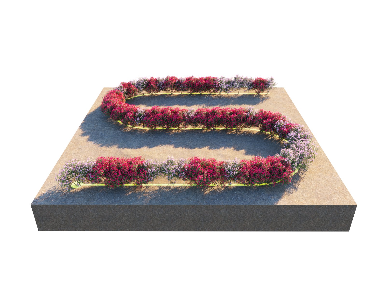
Spacing = 100
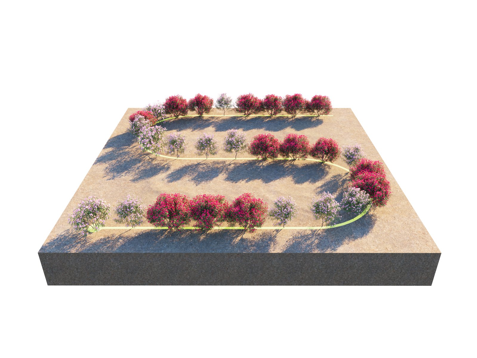
Spacing = 200
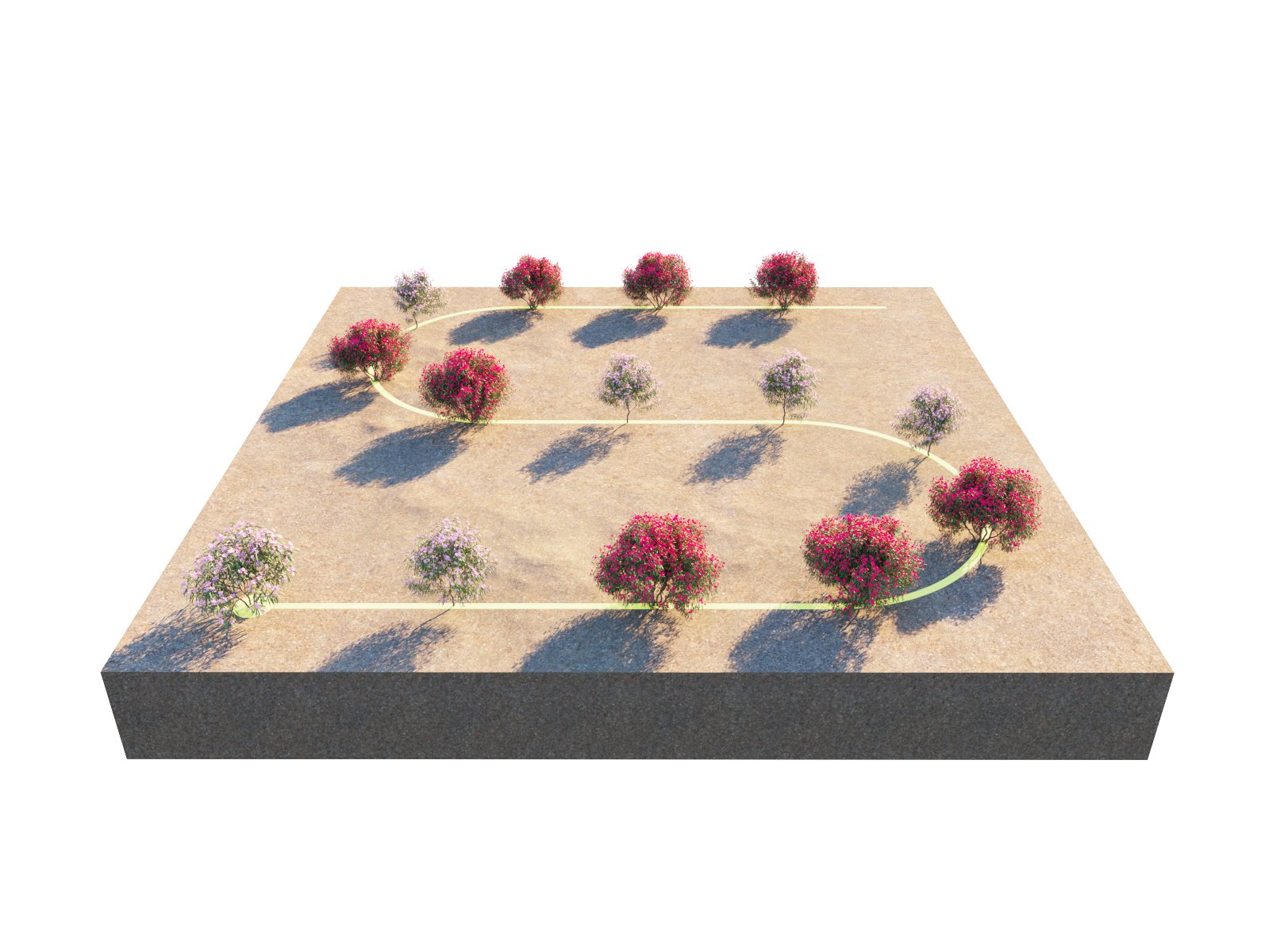
Spacing = 400
Example: Jitter
In this example, the Spacing under Spline Scattering is fixed to 200 inches, and the instances are randomly distributed within the spline.

Spacing = 200; Jitter = 0

Spacing = 200; Jitter = 100
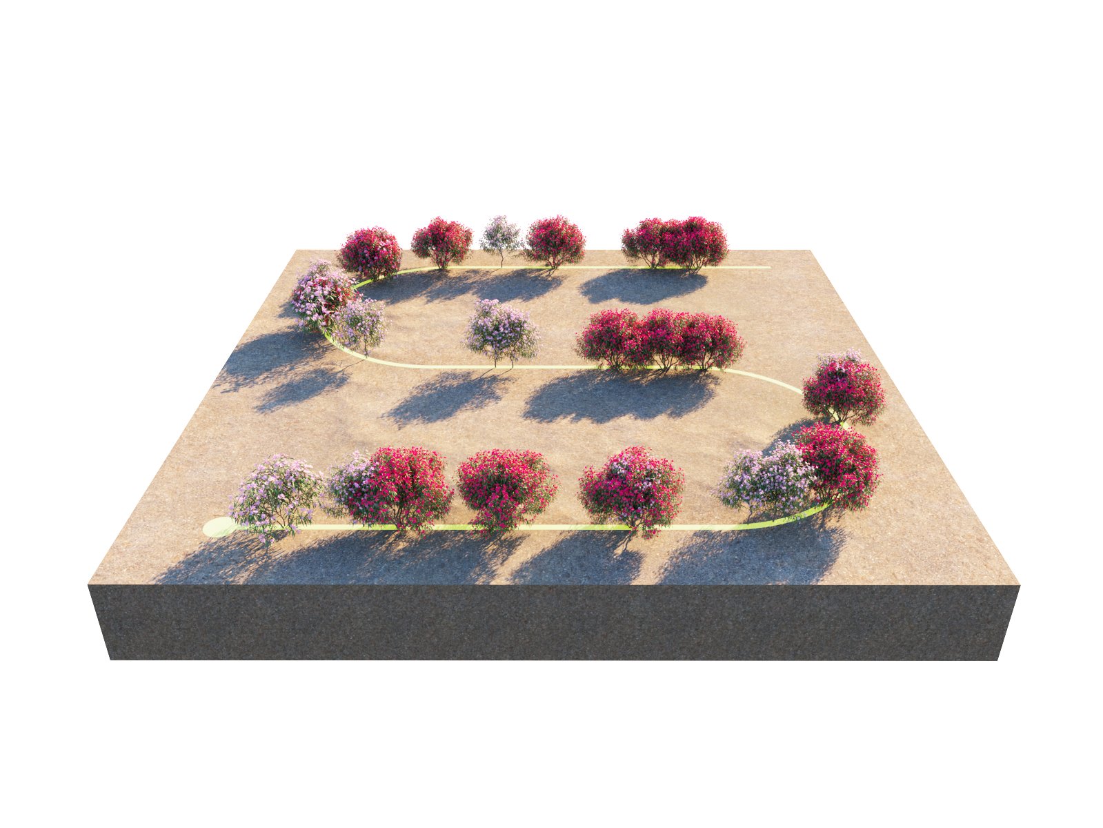
Spacing = 200; Jitter = 200
Example: Offset
When set to 100%, all instances replace the one after them, as the offset is equal to the whole value of the Spacing.
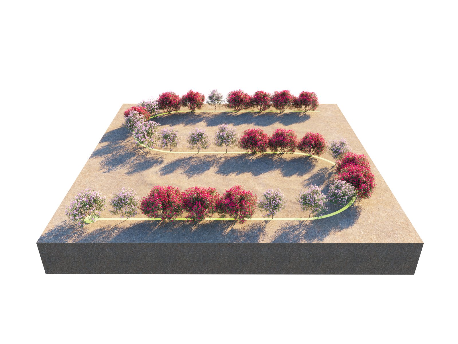
Spacing = 200; Offset = 0

Spacing = 200; Offset = 100

Spacing = 200; Offset = 200
Example: Follow amount
In this example, the Spacing is fixed to 200 inches, and the instances are randomly distributed within the spline.

Rotation Z ; Spacing = 200; Follow amount = 0

No Rotation values set; Spacing = 200; Follow amount = 50

No Rotation values set; Spacing = 200; Follow amount = 100
Example: Instance count
This example shows the exact instances count on a target object.
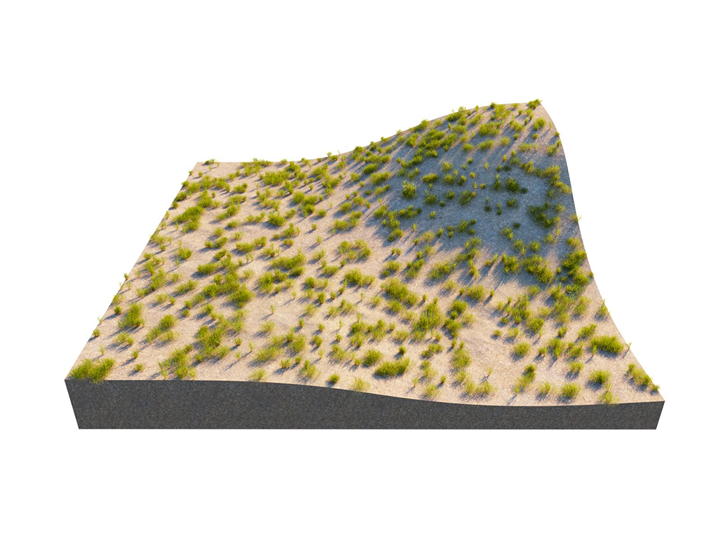
Count = 1000
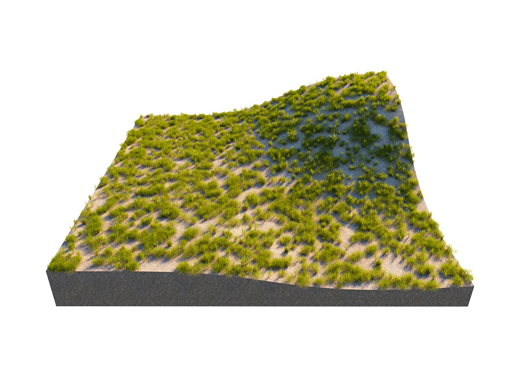
Count = 2500
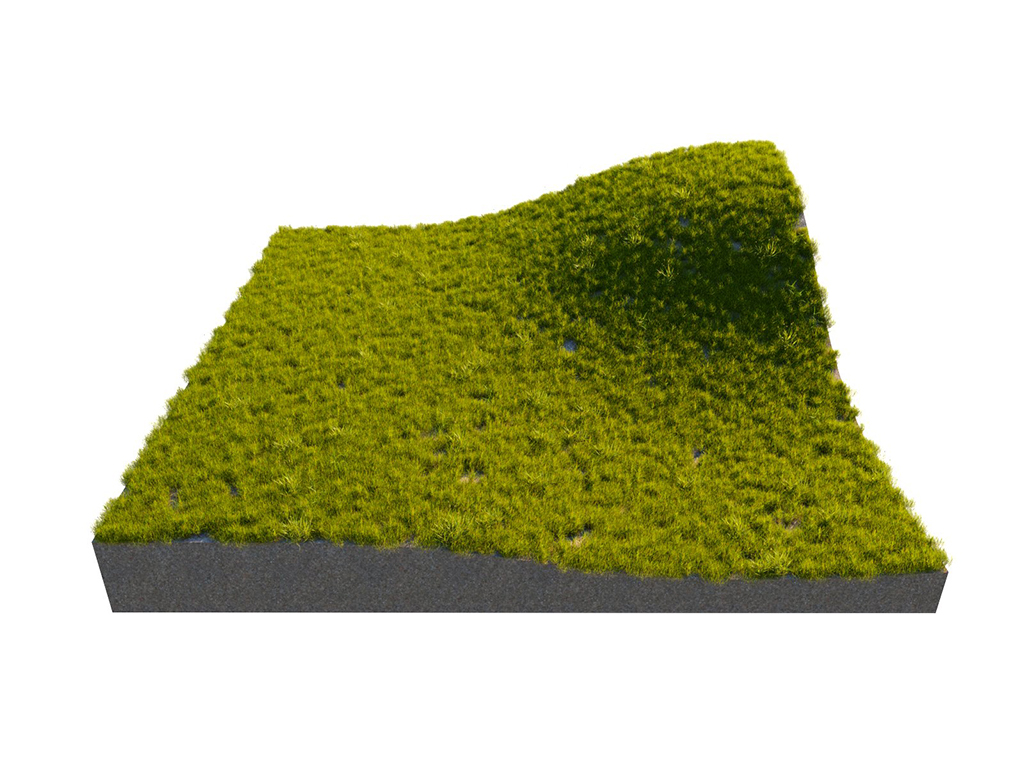
Count = 10000
Example: Square area
The number of instances here is determined by the count combined with the target object's surface size. The value specifies the length of the distribution area's side/edge.
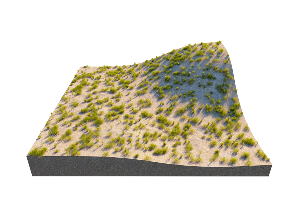
Count = 1000; Use area density = Off
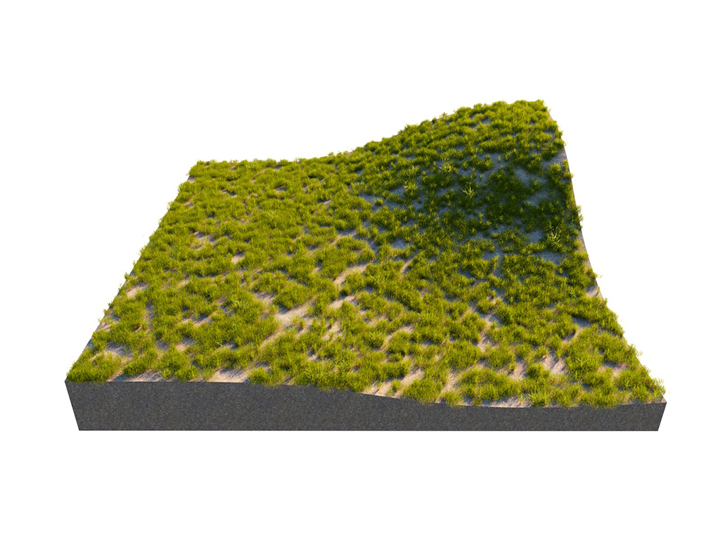
Count = 1000; Suqare area = 1000
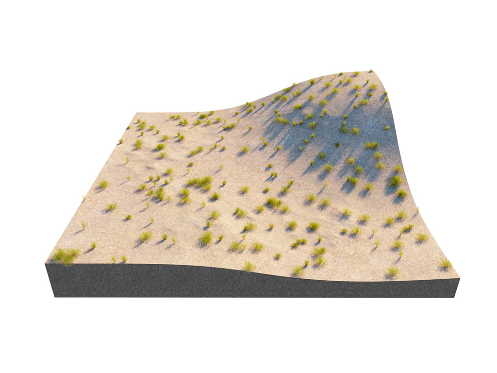
Count = 1000; Square area = 4000
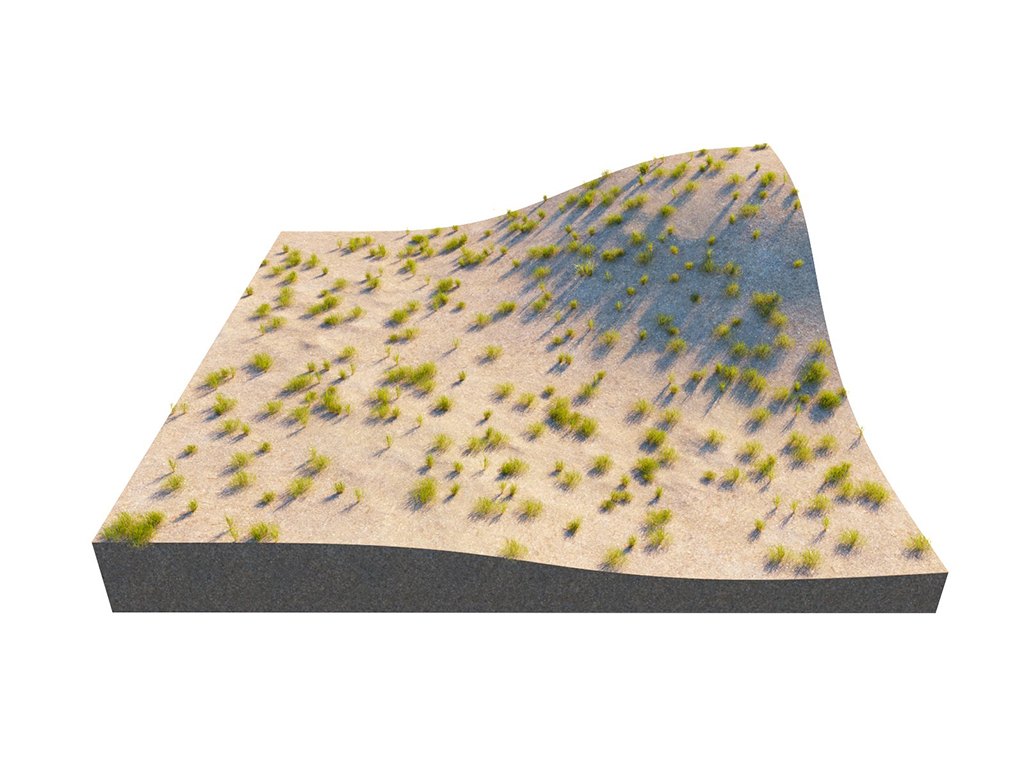
Count = 1; Square area = 100

Count = 1; Square area = 1000
Example: Surface Scattering Pattern
This example shows the different pattern types for surface scattering.
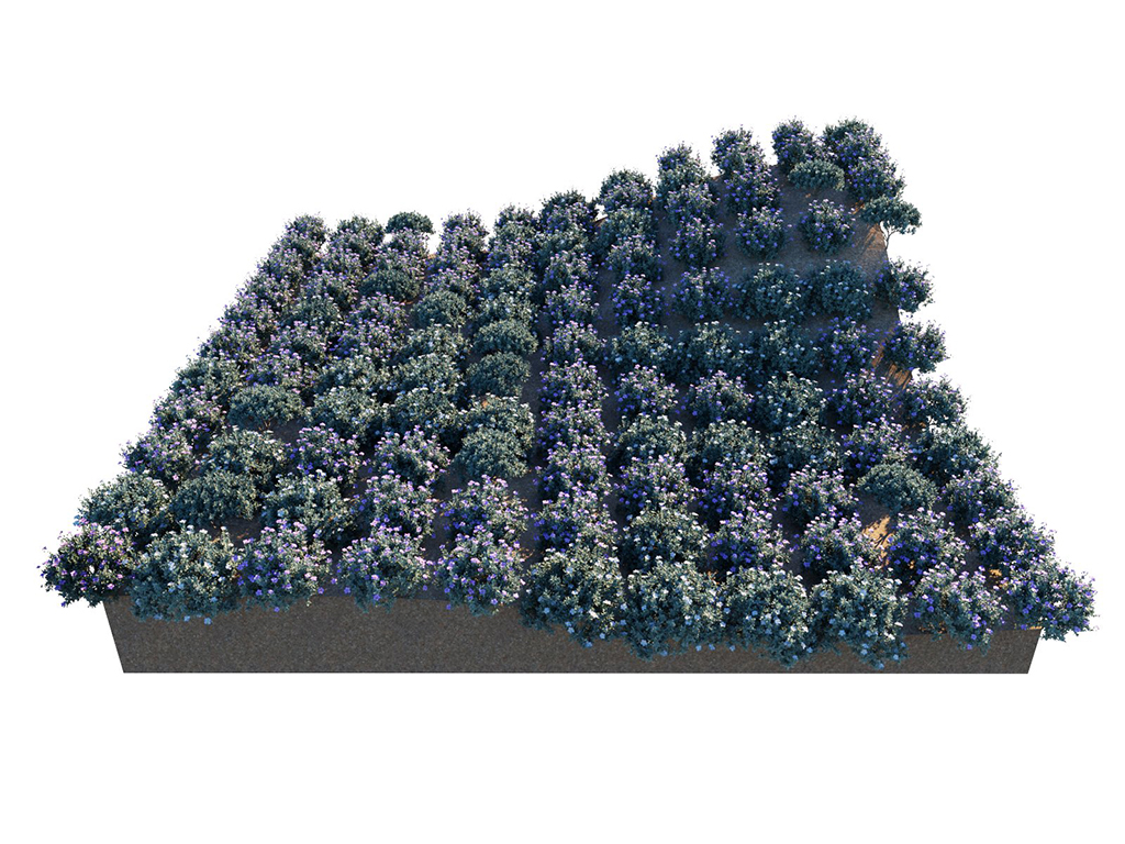
Spacing = 10; Pattern = Grid
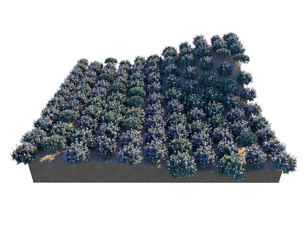
Spacing = 10; Pattern = Running grid
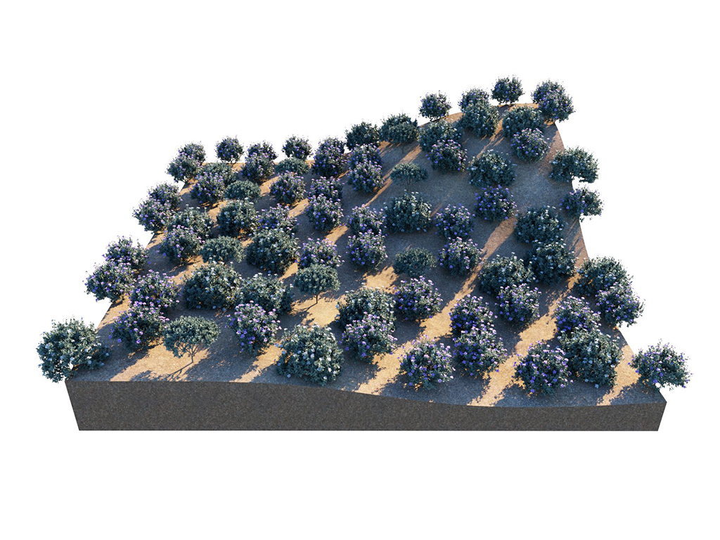
Spacing = 10; Pattern = Hex grid
Example: Surface Scattering Spacing
This example shows how the spacing parameter affects the distances between the instanced model objects.
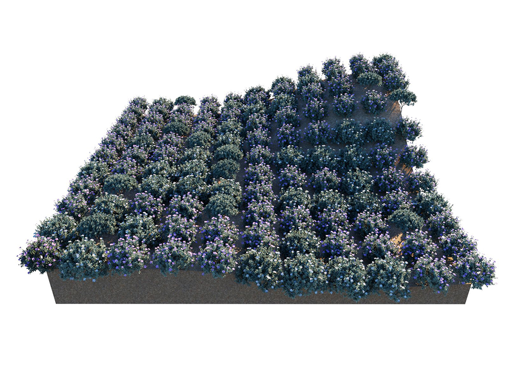
Pattern = Grid; Spacing = 10
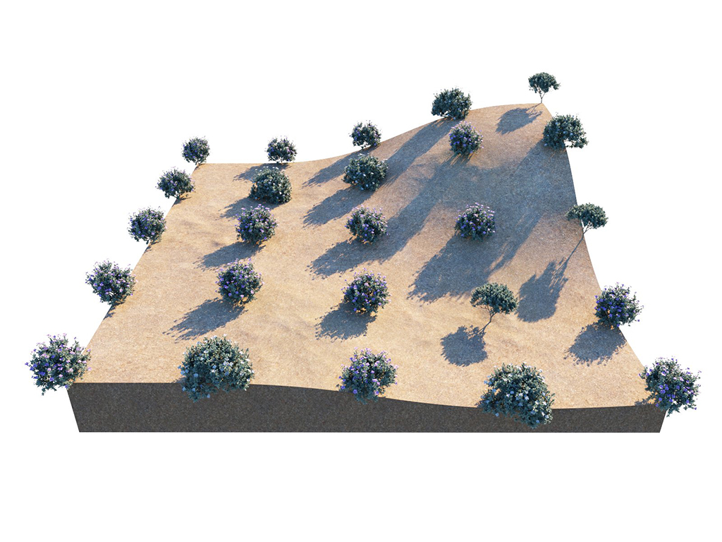
Pattern = Grid; Spacing = 25
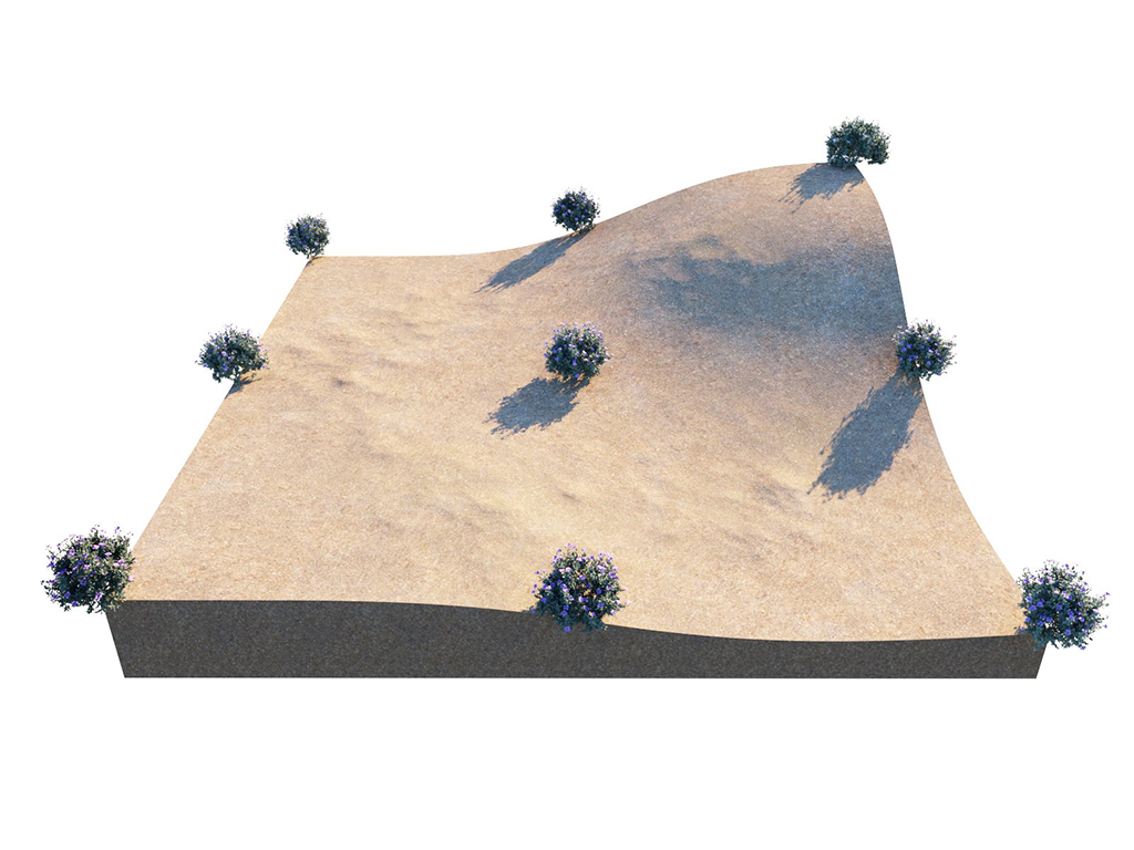
Pattern = Grid; Spacing = 50

Pattern = Grid; Spacing = U 10; V 25
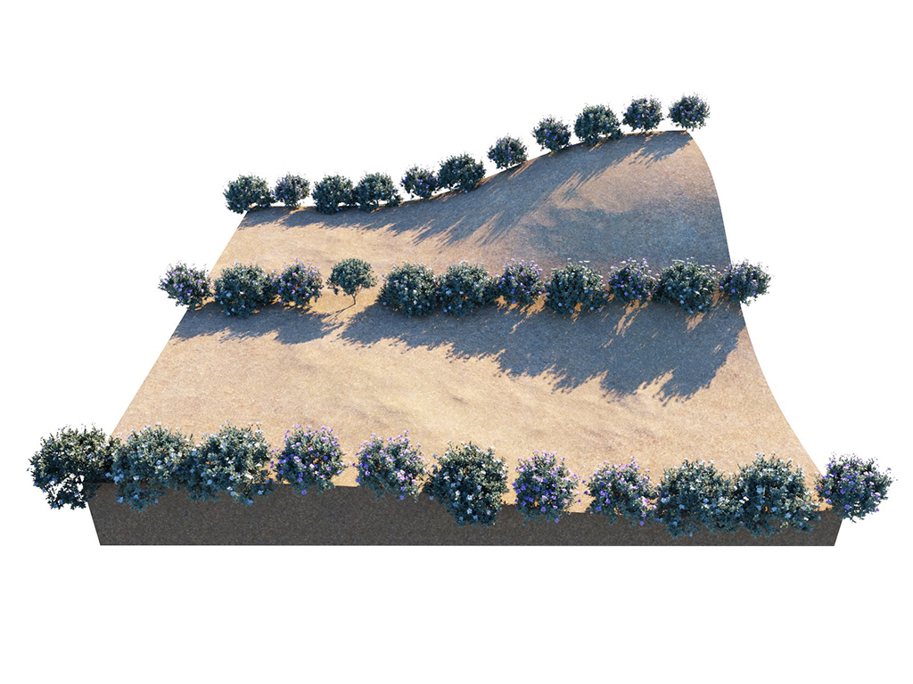
Pattern = Grid; Spacing = U 10; V 50
Example: Slope Limitation
The Min / Max slope angles remove instances based on the angle of the underlying geometry. These options can be used to remove geometry from steep areas as well as shallow areas.
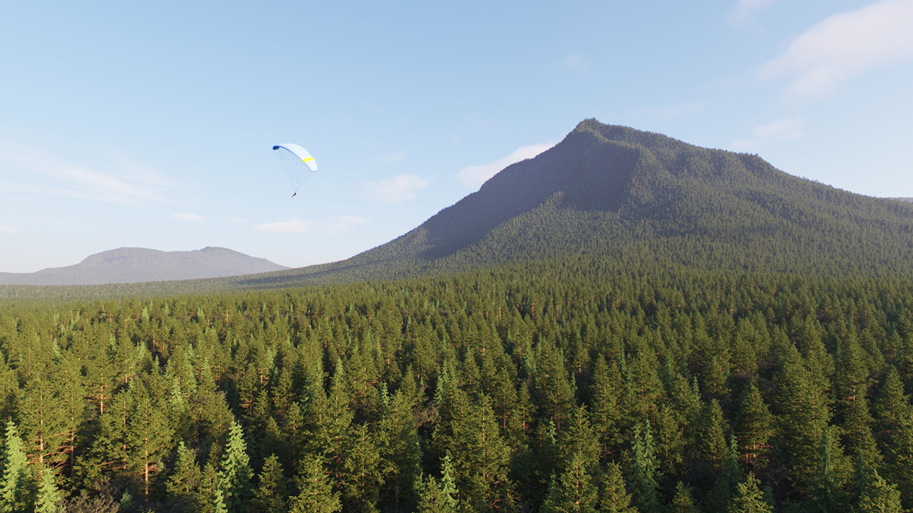
Slope limitation = disabled

Slope limitation enabled, Min/Max slope angle = 0.0 - 45.0
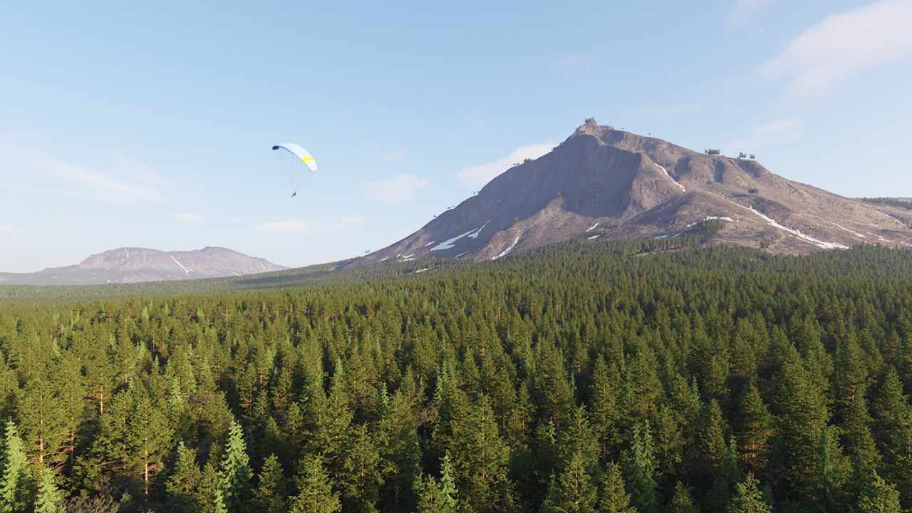
Slope limitation enabled, Min/Max slope angle = 0.0 - 20.0
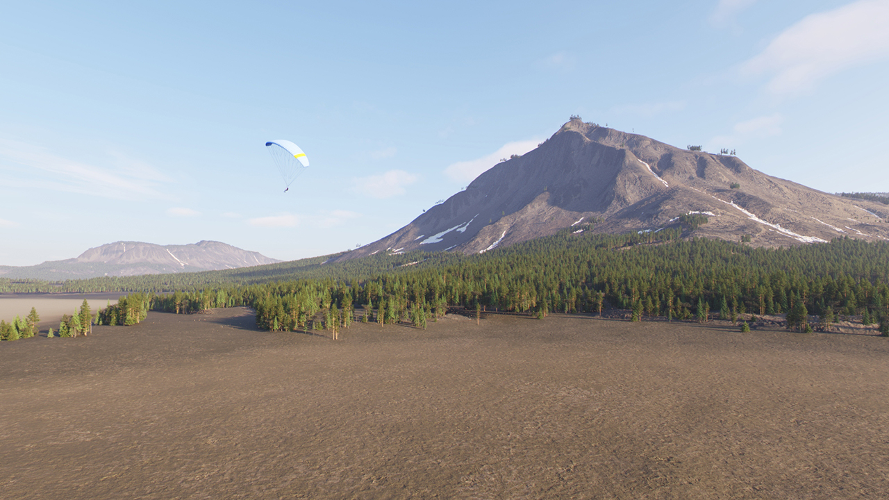
Slope limitation enabled, Min/Max slope angle = 5.0 - 20.0
Example: Rotation
This example is set with Surface Scattering Grid Pattern.

Rotation = X 0-0; Y 0-0; Z 0-0
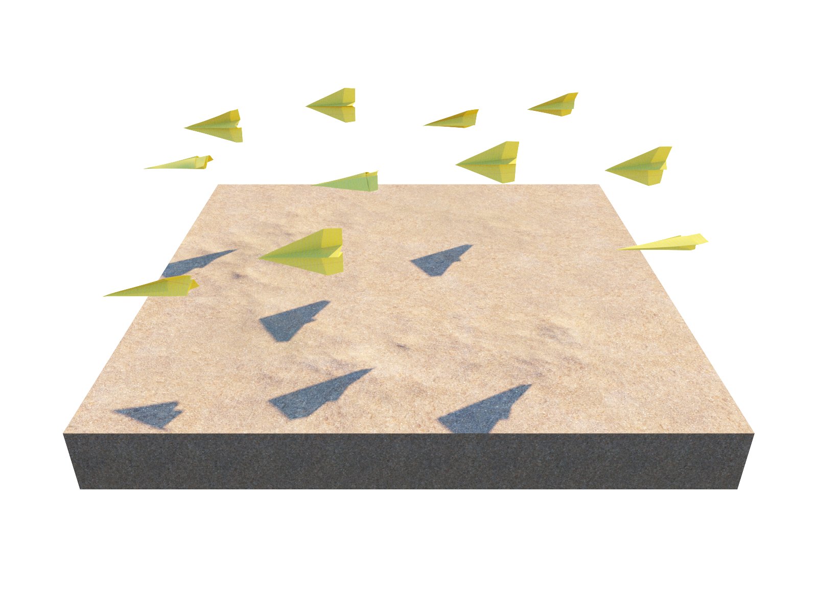
Rotation = X 0-90; Y 0-0; Z 0-0

Rotation = X 0-0; Y 0-90; Z 0-0
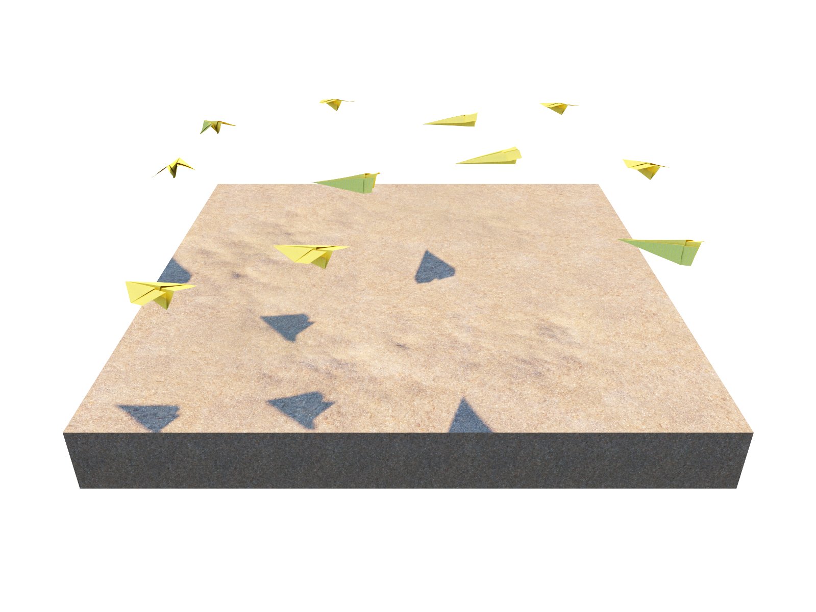
Rotation = X 0-0; Y 0-0; Z 0-90
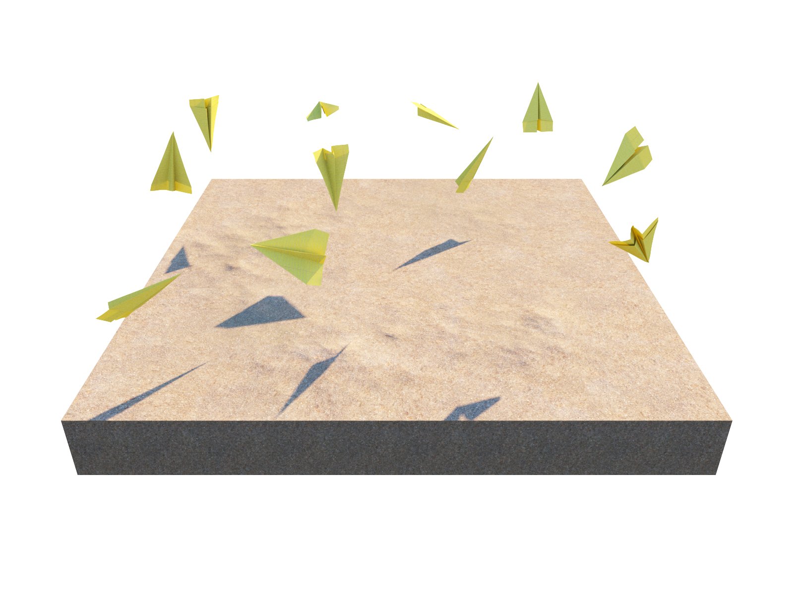
Rotation = X 0-360; Y 0-360; Z 0-360
Example: Stepping angle
This example is set with Surface Scattering Grid Pattern and Rotation = X 0-0; Y 0-0; Z 0-360
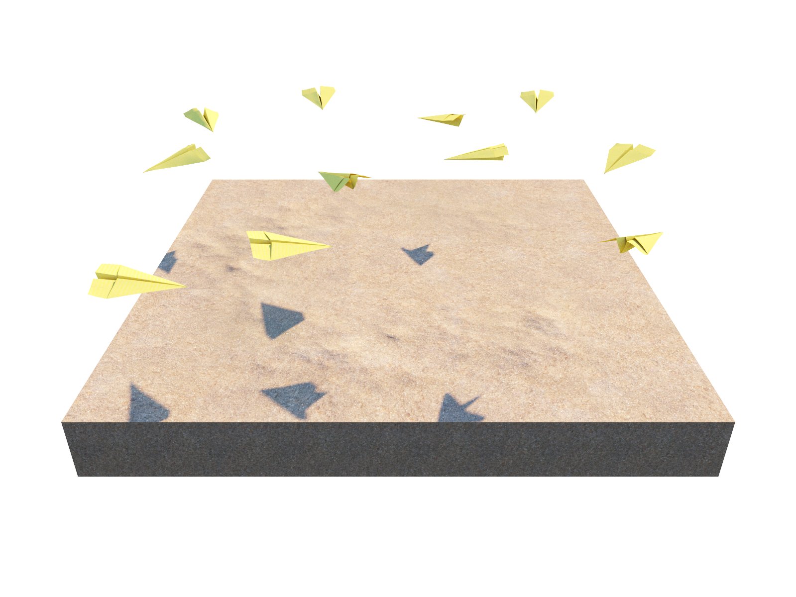
Stepping angle = Z 0
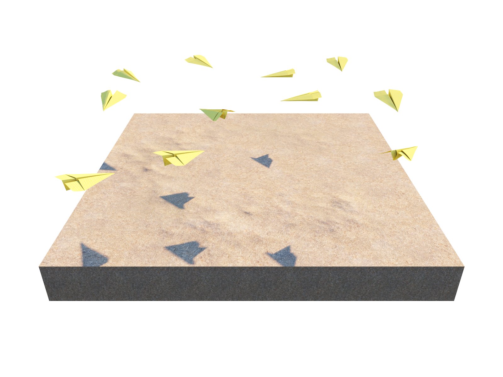
Stepping angle = Z 45

Stepping angle = Z 90
Example: Target object
In this example, the sunflower objects are scattered along a plane and the Look At option is enabled. A Sun is assigned as the Target object, and it is moved along the sky as if it was setting over the horizon. The Horizontal option is enabled, allowing the sunflowers to rotate more realistically. Slide through the images to see the movement of the sunflowers.

Example: Falloff distance
In this example, the sunflowers are looking at the blue butterfly. Adding Falloff distance creates an area around the Target object where the effect is applied. Setting the value to 0 applies the effect to the entire scattered geometry. Scrolling through the examples quickly reveals the area which remains affected.

Falloff distance = 0.0

Falloff distance = 3.0
Falloff distance = 9.0
Example: Scale
This example shows how the instanced model objects' scale is modified. See the difference of the scaling with Uniform scale on and off.
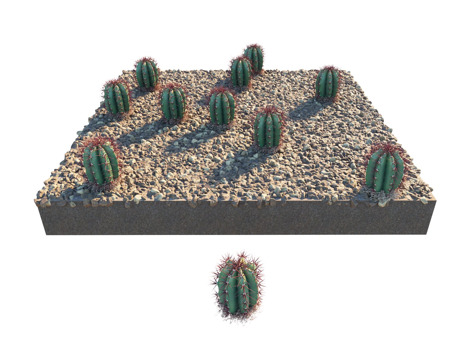
Scale Min/Max X = 100 - 100; Uniform scale = On

Scale Min/Max X = 100-200; Uniform scale = On
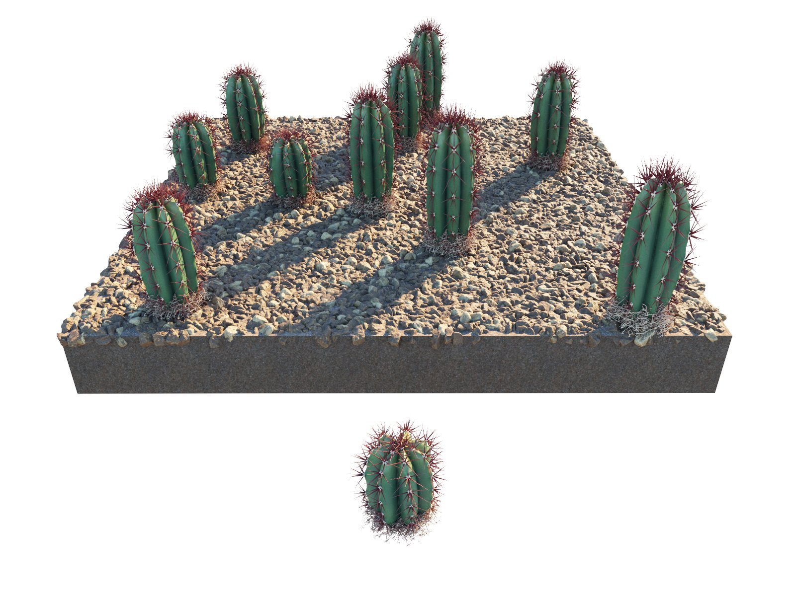
Scale Min/Max X = X 100-100; Scale Min/Max Y = 100-100; Scale Min/Max Z = 100-200; Uniform scale = Off
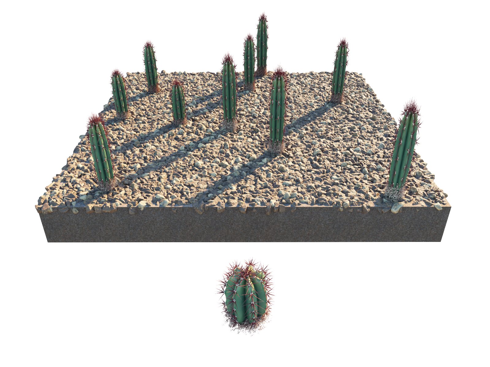
Scale Min/Max X = 50-50; Scale Min/Max Y 50-50; Scale Min/Max Z 100-200; Uniform scale = Off
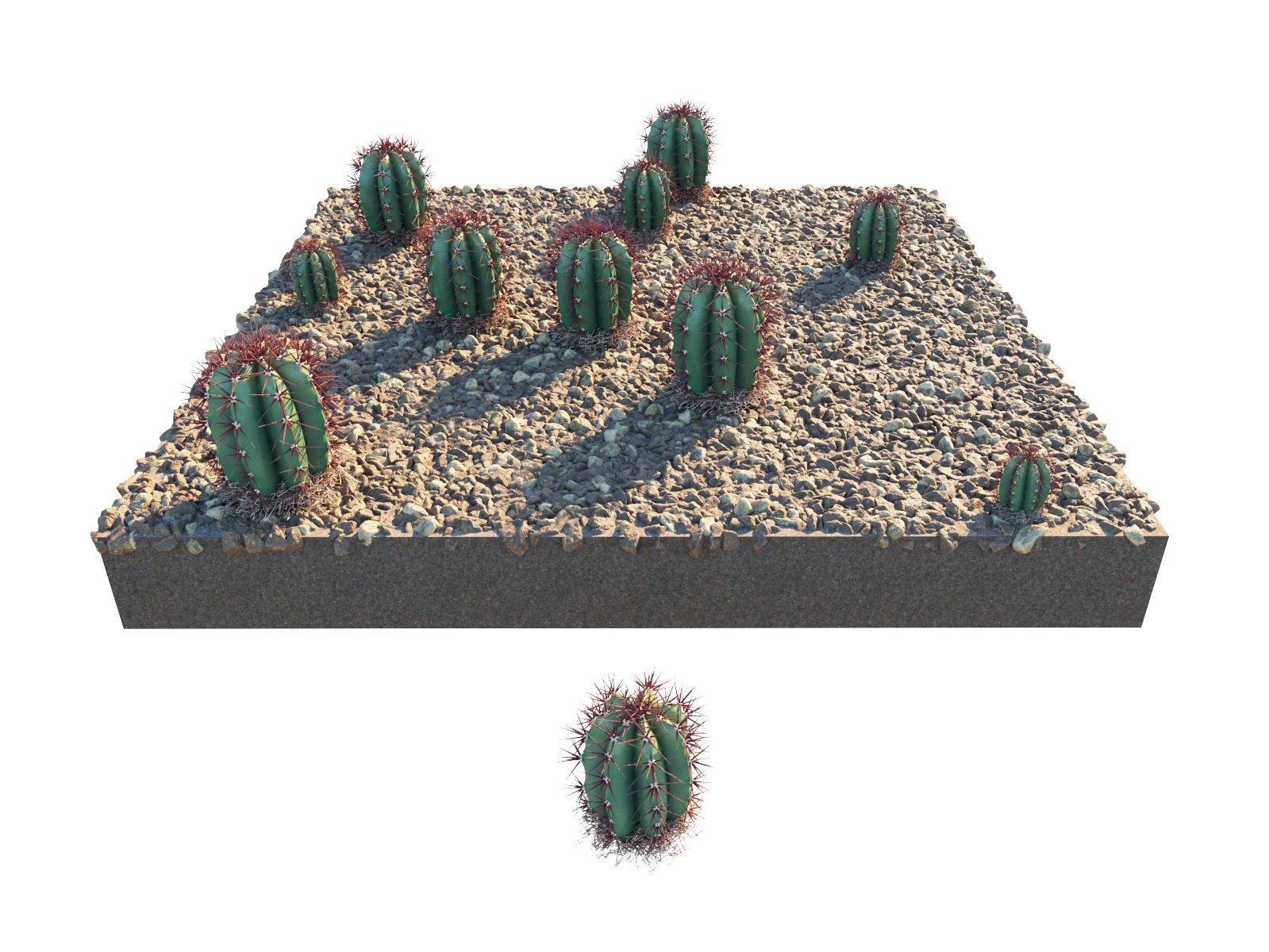
Scale Min/Max X = 50-150; Uniform scale = On; Stepping = 0
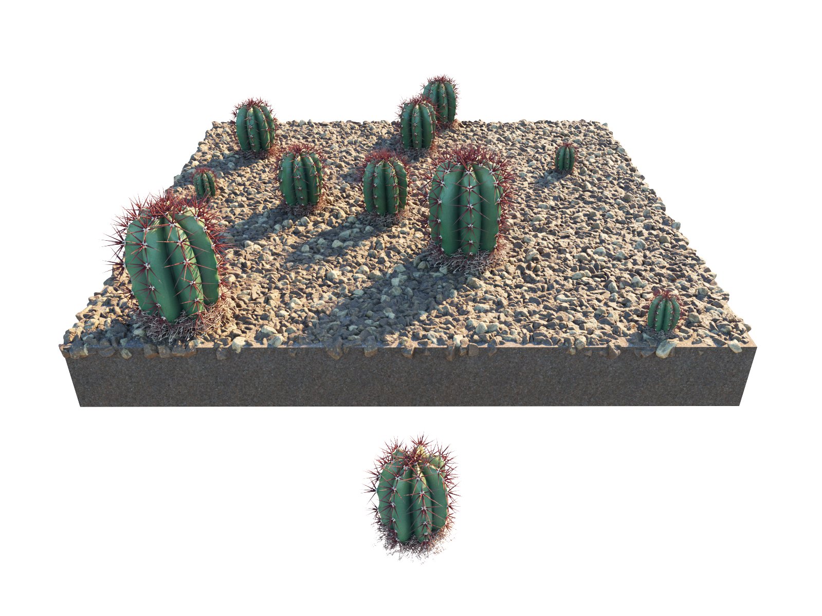
Scale Min/Max X = 50-150; Uniform scale = On; Stepping = 50
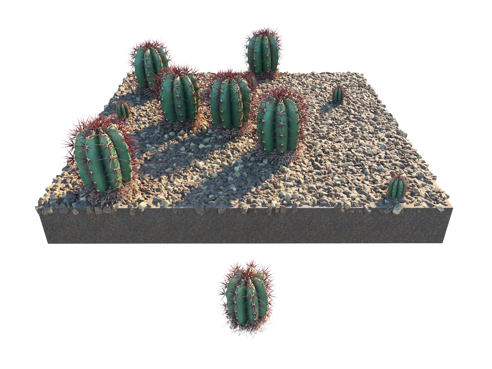
Scale Min/Max X = 50-150; Uniform scale = On; Stepping = 100

Scale Min/Max X = 100-100; Uniform scale = On; Preserve model scale = Off (model not scaled)
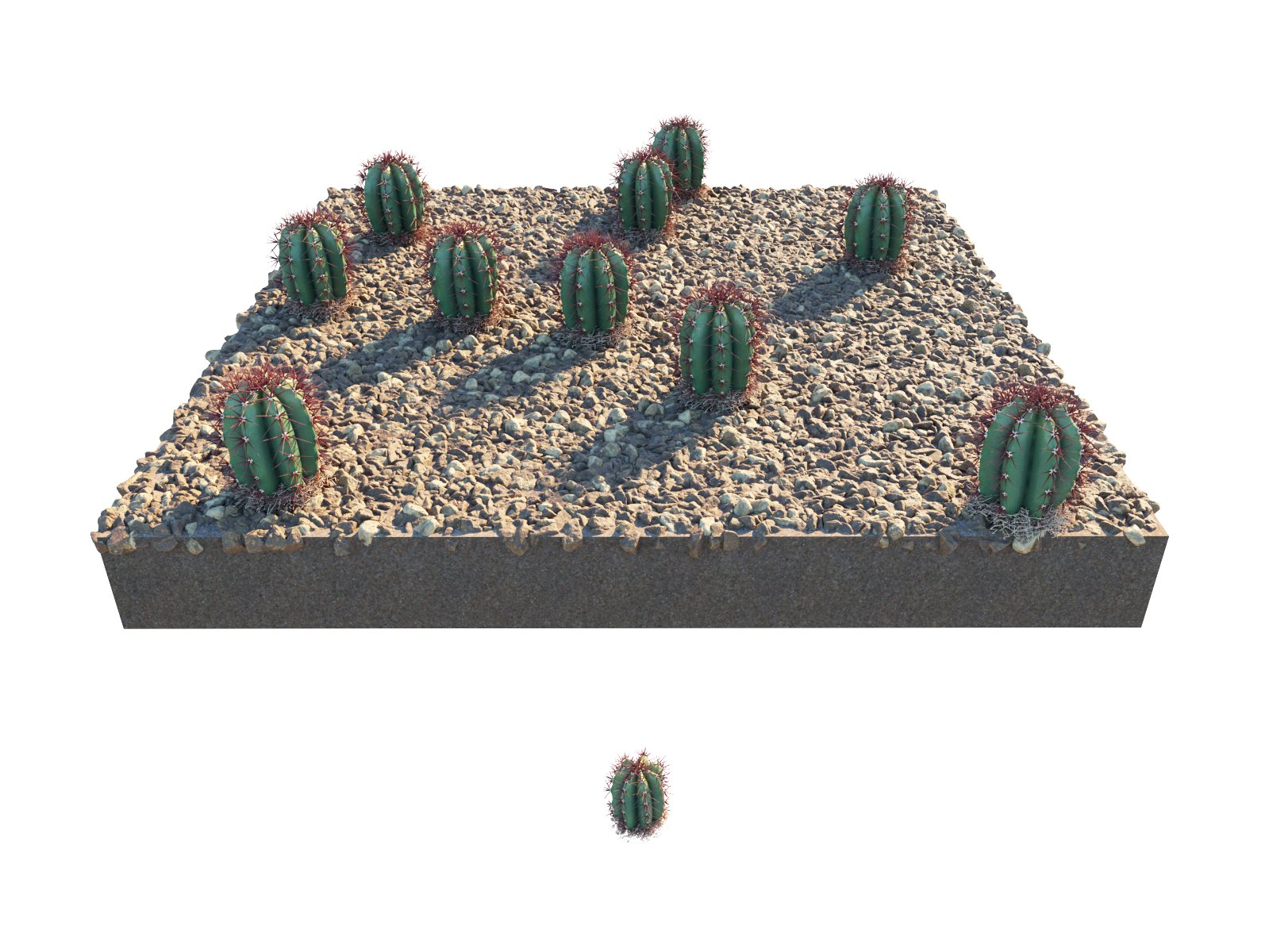
Scale Min/Max X = 100-100; Uniform scale = On; Preserve model scale = Off (model scaled down)
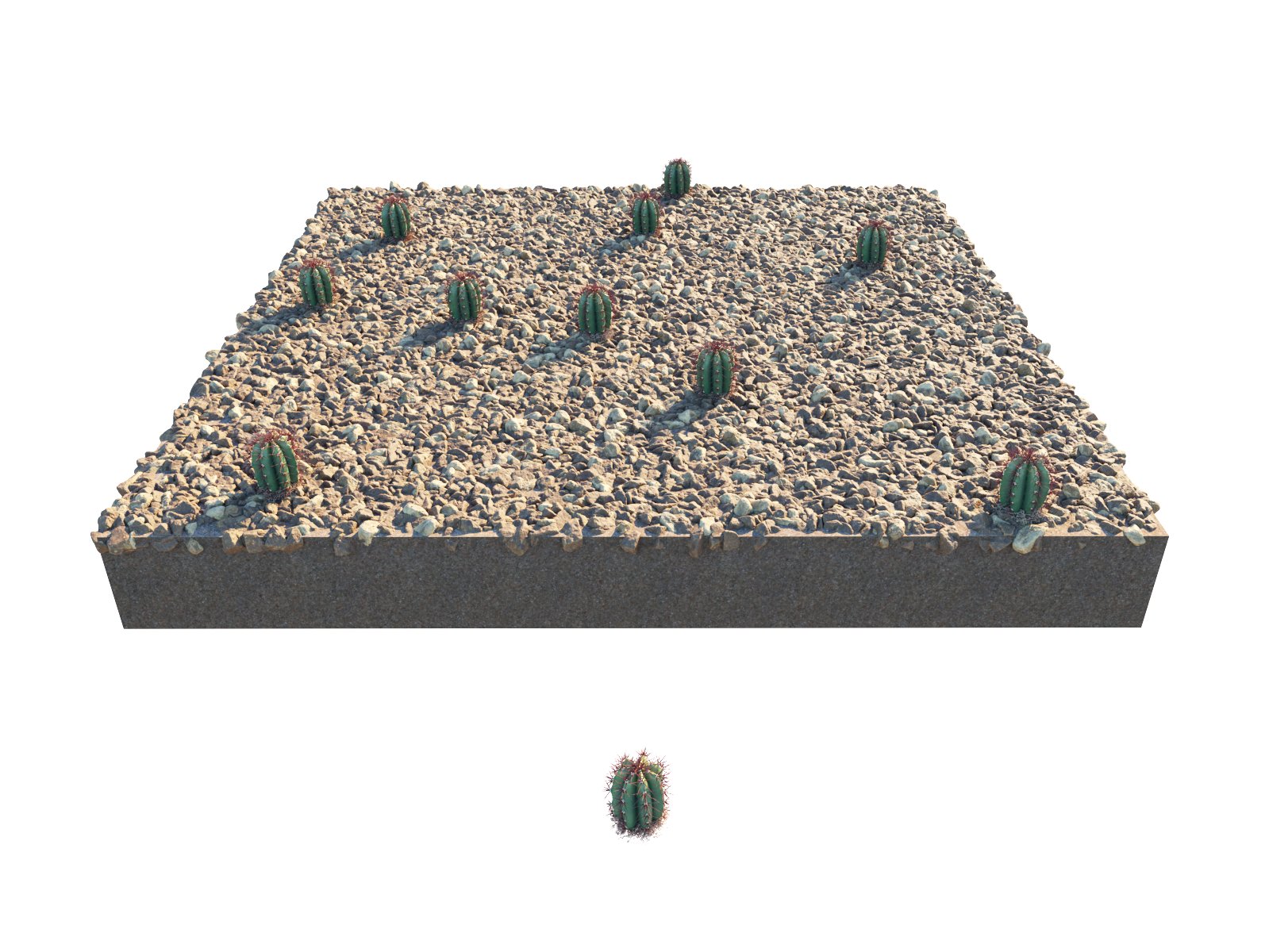
Scale Min/Max X = 100-100; Uniform scale = On; Preserve model scale = On (model scaled down)