Corona for 3ds Max
Chaos Scatter
This page provides information on using Chaos Scatter with Corona for 3ds Max.
Last updated 1 September 2026
This page provides information on using Chaos Scatter with Corona for 3ds Max.
Overview
Chaos Scatter lets you quickly and efficiently populate surfaces, splines, and volumes with vast numbers of objects. Its major features include:
- A library of ready-to-use presets available in Chaos Cosmos
- Ability to edit individual instances
- Slope and altitude limiting for the scattered instances (no trees growing out of cliffs!)
- Clustering of instances
- Edge trimming (removing any elements of scattered models which stick outside of the defined area)
- Including/excluding scattering areas using splines (closed or open) and objects
- Surface color map (coloring scattered instances based on pattern textures on rugs, etc.)
- Limiting scattering only inside camera field of view (camera clipping)
- Efficient viewport display
- and more...
UI Path: ||Scatter Toolbar|| > Chaos Scatter button


Tutorial: Using Chaos Scatter with Corona for 3ds Max
www.youtube.com
Objects
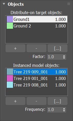
Distribute-on target objects – List of scene objects used as the base for distributing the scattered instances.
"+" button - Allows picking scene objects.
"-" button - Removes the highlighted object from the list.
"[...]" button – Opens a dialog where you can manually add and remove scene objects to the list.
Factor – Available only in Random Surface and Bounding Box scattering. In either case, if the scattering is defined just by the Count option, it works as a relative weight factor determining how many instances get scattered for the currently selected distribute-on object. Alternatively, in case of scattering instances to reach some density defined by Count and Per square/cube options, it works as a density factor (multiplier) affecting the final density there.
Instanced model objects – List of scene objects which are being scattered on the distribute-on objects.
"+" button - Allows picking scene objects.
"-" button – Removes the highlighted object from the list.
"[...]" button – Opens a dialog where you can manually add and remove scene objects to the list.
Frequency – Available only if there is more than one instanced object. Sets the frequency of the currently selected instanced object relative to others.
Examples: Objects
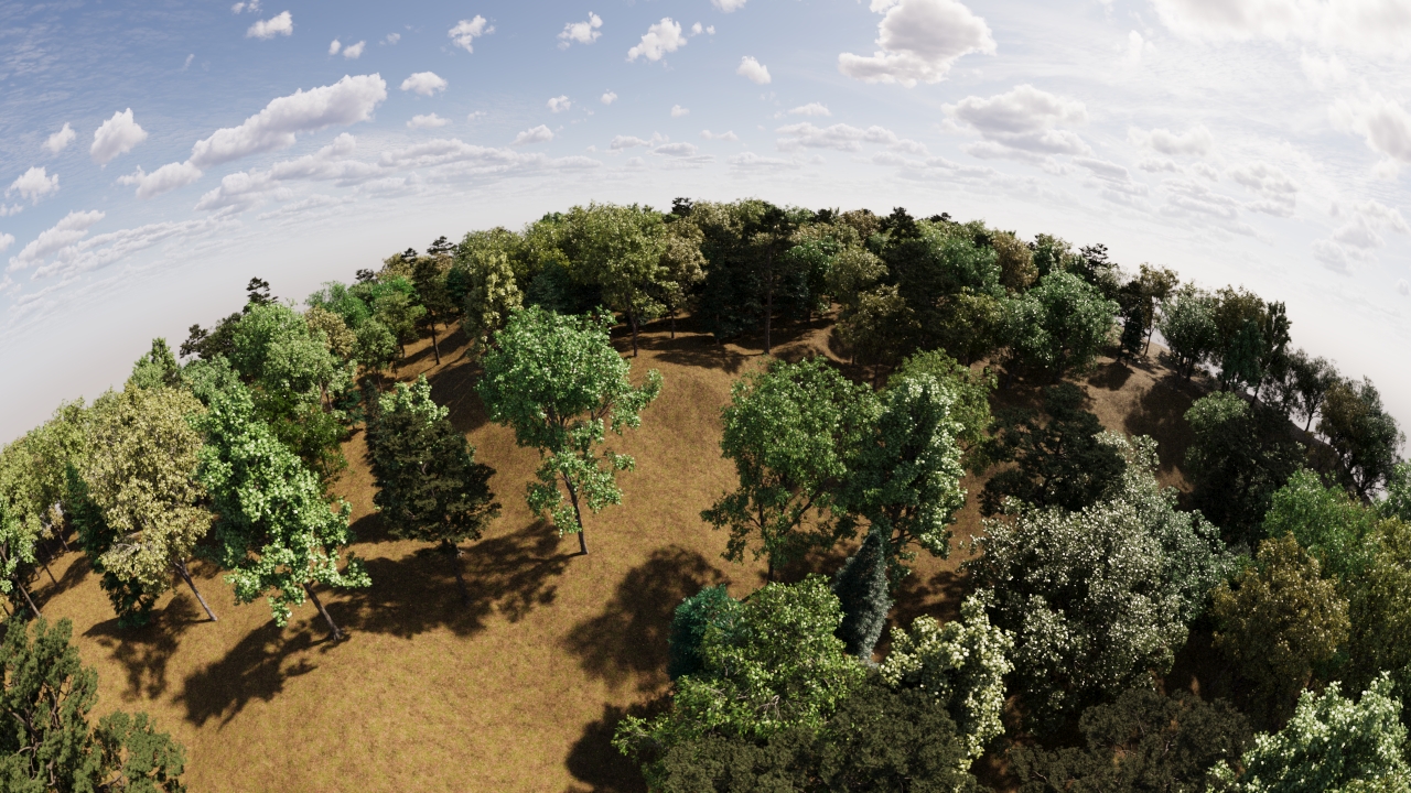
In case of scattering trees on the ground, the tree models are used as Instanced model objects and the ground plane is used as the Distribute-on target object.
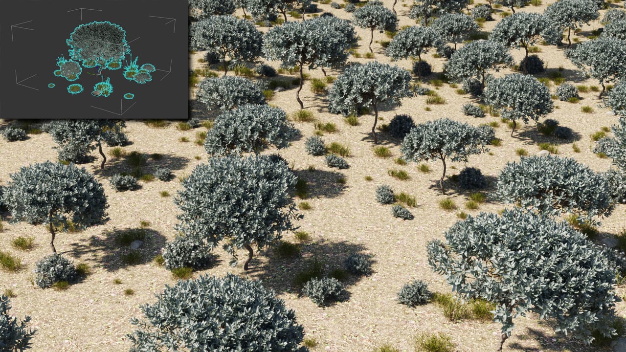
A group consisting of multiple objects (shown in the top-right corner) scattered on top of a plane. You can scatter object hierarchies too.
Display & Limits
Viewport
Instances
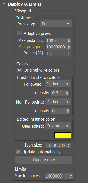
Previz type – Selects how to display scattered instances in the viewport. Affects viewport performance.
None – Instances are not displayed at all.
Dot – Each instance is displayed as a single dot.
Box – Each instance is displayed as a solid box.
Wire box – Each instance is displayed as a wire box.
Full – Each instance is displayed as the full mesh.
Point cloud – Displays each instance as a point cloud.
Adaptive previz – Enables Adaptive Full previz mode, which improves responsiveness in case of frequent viewport redraws and large number of instances. In this mode scatter will draw part of instances as full mesh and the rest as boxes, while the user operates actively the viewport, frame slider or the scatter itself.
Max instances – Maximum number of scattered instances being displayed in the viewport. When this limit gets exceeded, some instances are randomly hidden. If increasing this number would display more instances, the label is colored.
Max polygons – Maximum number of polygons (forming scattered instances) being displayed in the viewport. When this limit is exceeded, the instances preview models will be optimized/simplified. If the polygon limit value is below the total polygon of the fully previewed instances the label is colored in orange. If the polygon limit value is below the lower possible polygon number for the visible instances it is colored in blue.
Points – Percentage of points to display when Point cloud representation is selected in the Previz type selection.
Colors
Original wire colors – Selects whether to use wire colors of original instances objects when displaying their instances as dots, point clouds, or wire boxes in the viewport.
Brush Instances Colors
Following – Selects how to color following painted instances in the viewport: Original, Darker or Custom.
Intensity – Sets the intensity of color darkening for following painted instances in the viewport. The value ranges in [0;1], where 0 means full darkening and 1 means no darkening.
Non-Following – Selects how to color non-following painted instances in the viewport.
Edited Instance Color
User Edited – Selects how to color edited instances in the viewport: Original, Darker or Custom.
Icon size – Sets the display size of the selected Scatter object's gizmo.
Update automatically – When disabled, scattering is not recomputed if any of the distribute-on/instanced objects change. The scattering is always recomputed if any parameters of the Scatter object itself change, regardless of this option.
Update now – Forces recomputation of the scattering.
Limits
Max instances – Limits the maximum number of scattered instances. Note that there is always another mode-dependent parameter (spacing, density, or count) which determines how many instances to scatter. This parameter is intended as a constant value "safety measure" to prevent crashes/freezes from scattering too many instances, e.g. when setting the density too high.
Examples: Display & Limits
Previz Type

None

Dot
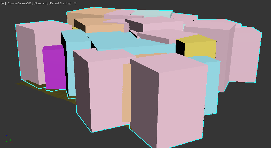
Box

Wire Box
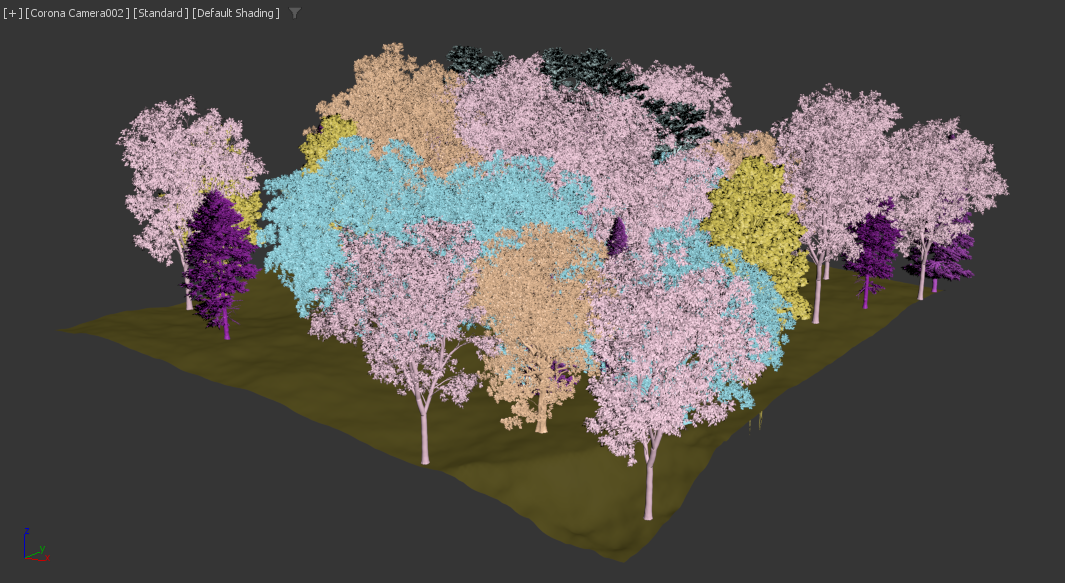
Full

Point Cloud
Adaptive Previz and Limits
Chaos-Scatter-adaptive-previz
mp4
28 MB
Scattering
Scatter Lister – Shows a lister allowing to inspect and control all Scatter objects in the scene.
Enable – Enables the scattering.
Scattering type drop-down:
1D - On splines – Scatters instances along splines. Works with both open and closed splines.
2D - On surfaces – Scatters instances on the surface of the selected objects. Works with closed splines too, treating the spline area as the surface to scatter on.
3D - In bounding box – Scatters instances inside the bounding boxes of the selected objects.
Random seed – Determines the particular random distribution used. Changing the value makes random permutations of the scattered objects.
Temporal consistency – When enabled, instances get scattered in the selected Rest-pose frame and stick to the surface even if it deforms in other frames. When disabled, instances get scattered in each frame from scratch, which may lead to instances popping in and out. If it is combined with the Avoid collisions option, non-colliding instances in the Rest-pose frame are still allowed to collide in other frames.
Rest-pose frame – Specifies the frame with which the scattering is consistent at all other frames.
Avoid collisions – When enabled, the instances which collide with other ones are discarded, resulting in no overlaps between instances. Note that when using this feature, the real number of created instances may be lower than the number specified in the settings.
Spacing – This value is a multiplier for enlarging/shrinking the bounding boxes used to detect and remove collisions of the scattered objects. Use lower values to achieve a higher density of the scattered objects at the cost of some minor collisions. Use higher values to keep scattered objects farther apart from each other.


Examples: Scattering

Scattering mode: 1D - On splines

Scattering mode: 2D - On surfaces
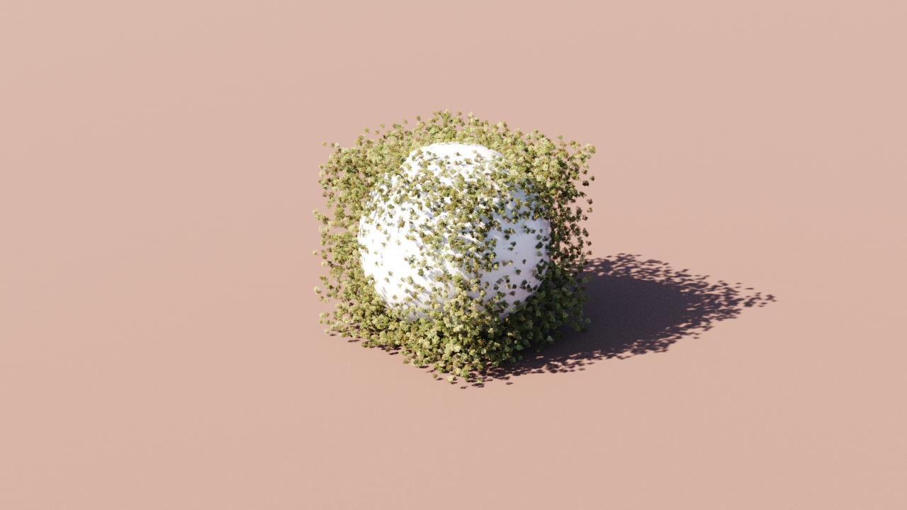
Scattering mode: 3D - In bounding box
Chaos Scatter Lister
The Chaos Scatter Lister is availabel from the Scatter toolbar > Open Chaos Scatter Lister, as well as from an existing scatter object’s Scattering rollout > Scatter Lister. It allows you to trun on and off all scatter objects in your scene, adjust their wire color, preview type, specify point, count, seed, etc. You can also control collisions and delete or update all scatter objects in bulk.

Example: Mutual Collission Avoidance

Original, Mutual collission avoidance is off

Mutual collission avoidance is

Mutual collission avoidance is 50%

Mutual collission avoidance is 200%
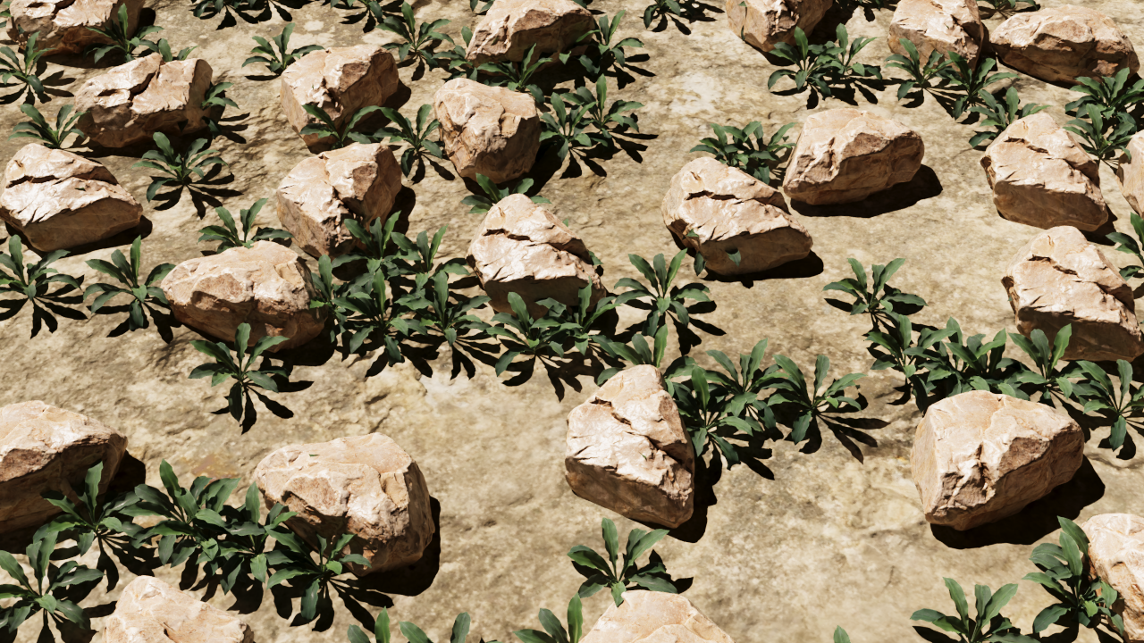
Both groups are set to None
Click here to see the setup...


One group is set to None
Click here to see the setup...


One priority is set to 2
Click here to see the setup...

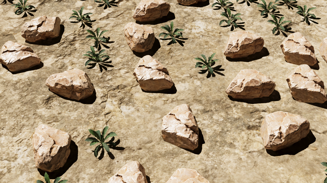
Same groups and same priority
Click here to see the setup...

Camera Clipping
Enable – When enabled, scattering is limited only to the camera view and instances which are not visible are clipped away. It is an optimization - it may improve scene parsing performance and lower memory requirements, however it can cause missing reflections/shadows. To compensate for this you can use the Extend view parameter.
Active render camera – Clips the instances based on the camera view used for rendering. The clipping is not visible in the viewport, unless changing clipping parameters or running IR. This is because otherwise the clipping would be too intrusive during regular scene work.
"None" object picker – Uses a selected camera for the clipping. In this case, the clipping is always visible.
Extend view – Specifies a uniform extension to the camera view in all directions (as distance), adding an extra zone beyond the camera view (behind the camera too) where the instances are not clipped. This is useful for ensuring correct shadows or reflections from instances that would otherwise be clipped.
Near and Far overrides – Specifies the near and far threshold distances from the camera. Instances close than the "near" value and farther than the "far" value are clipped away.

Examples: Camera Clipping
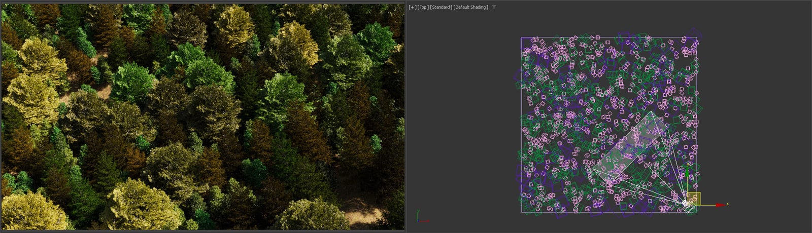
Camera clipping disabled

Camera clipping enabled

Camera clipping enabled and "Extend view" set to 5 meters
With camera clipping disabled, the ground plane is fully covered with the scattered instances. When camera clipping is enabled, it limits the instances to the visible area only. The Extend view option can be used to expand the area where the instances are visible. This is useful, for example, to make sure that trees growing close to the camera are not removed.
Surface Scattering
Random Distribution
This mode scatters instances randomly on all mesh and closed spline distribution objects. It is enabled by default.
Random – Scatters randomly on all mesh and closed spline distribution objects.
UV Channel – Specifies which of the UV channels of the distribution objects to consider. When a Custom map is used, this option is disabled and the UV channel is placed in the Bitmap settings is used instead.
Pattern – Choose from the drop-down list which pattern to use for random scattering:
None – Scatters instances uniformly and randomly only based on density (Per square option)
Custom map – Scatters instances randomly based on a custom texture map placed in the Map slot.
Distorted streaks high – Scatters instances randomly in streaks with high density based on a predefined map.
Distorted streaks low – Scatters instances randomly in streaks with low density based on a predefined map.
Groups high – Scatters instances randomly in groups with high density based on a predefined map.
Groups low – Scatters instances randomly in groups with low density based on a predefined map.
Fractal patches high – Scatters instances randomly with high density based on a predefined fractal map.
Fractal patches low – Scatters instances randomly with low density based on a predefined fractal map.
Straight lines high – Scatters instances randomly in straight lines with high density based on a predefined map.
Straight lines low – Scatters instances randomly in straight lines with low density based on a predefined map.
Stretched patches high – Scatters instances randomly in stretched patches with high density based on a predefined map.
Stretched patches low – Scatters instances randomly in stretched patches with low density based on a predefined map.
Count – Defines an exact number of instances to scatter - either overall, or per area in the case of scattering defined by density (Per square option). The number is always limited by the Max. limit option.
Per square – When enabled, the number of instances to scatter is defined by density (Count per square having the given edge length). The number of instances is always limited by the Max. limit option. The specified value is the edge length of a square defining an area for computing the scatter density. The length is measured in world units.

Example: Random Distribution

Pattern = None
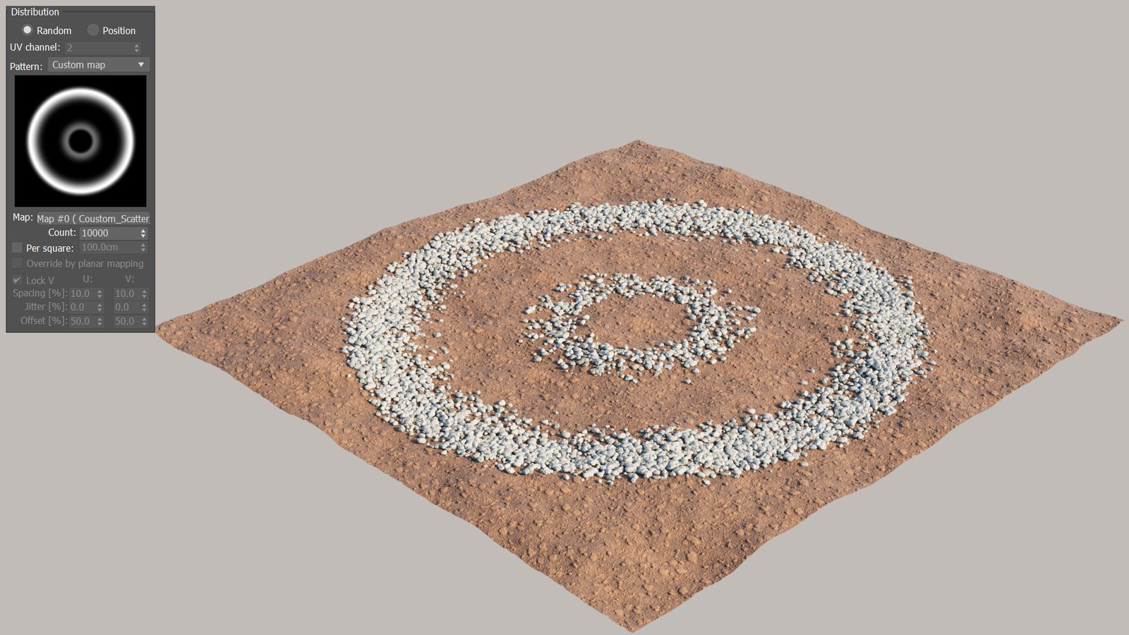
Pattern = Custom-map
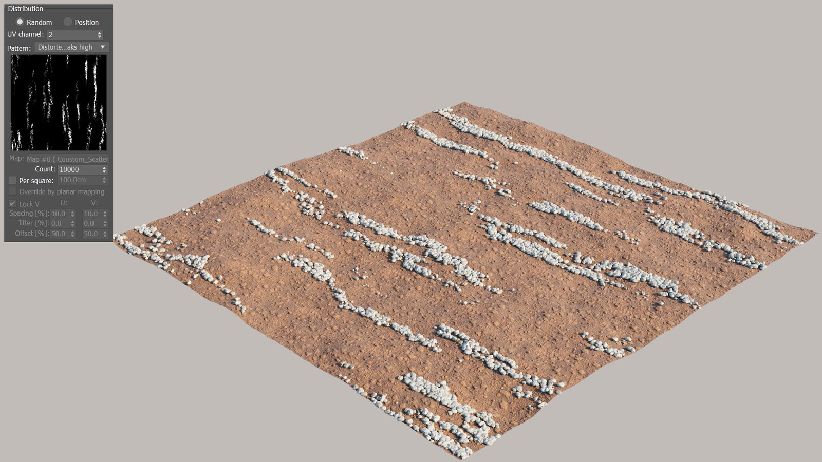
Pattern = Distorted-streaks-high
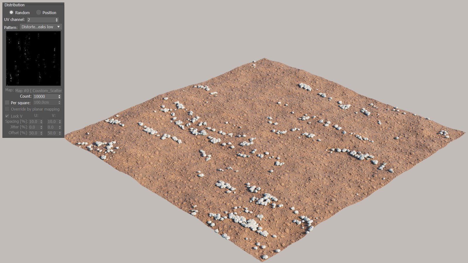
Pattern = Distorted-streaks-low

Pattern = Groups-high
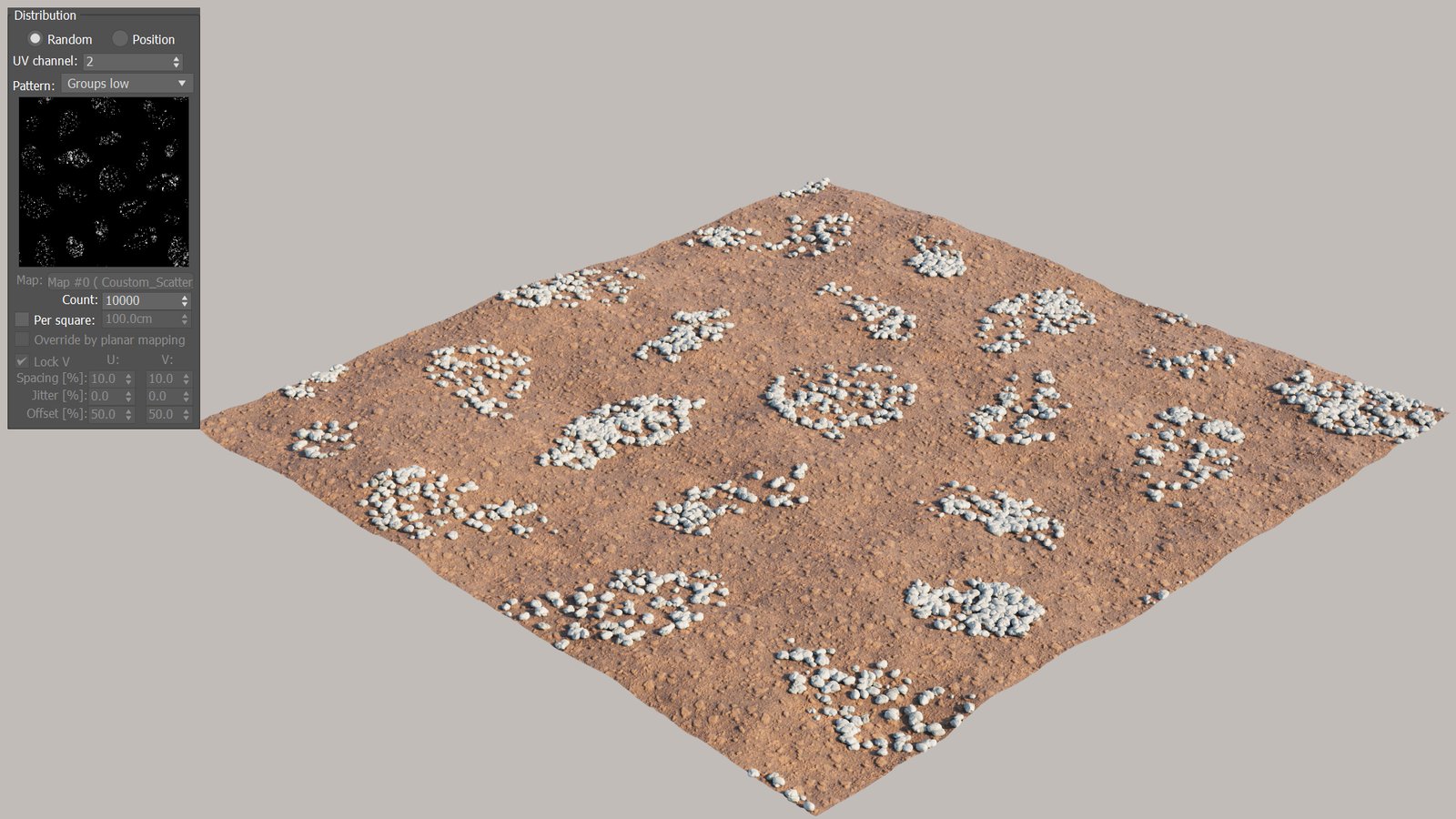
Pattern = Groups-low

Pattern = Fractal-patches-high

Pattern = Fractal-patches-low

Pattern = Straight-lines-high
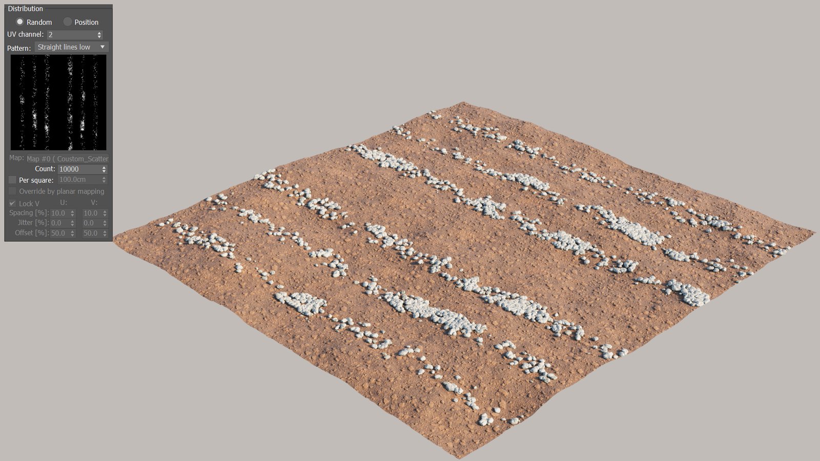
Pattern = Straight-lines-low
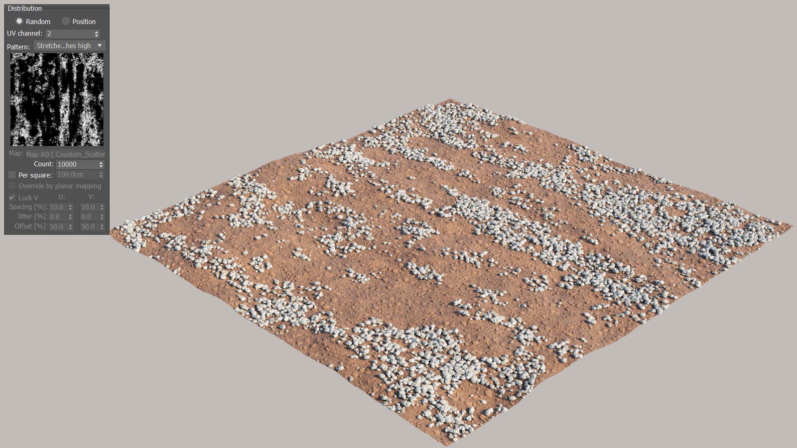
Pattern = Stretched-patches-high

Pattern = Stretched-patches-low
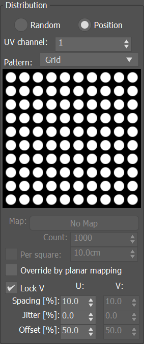
Position Distribution
This mode specifies the position of the instances based on a pattern.
Position - Use UVW mapping to scatter the instances in regular patterns.
UV Channel – Specifies which of the UV channels of the distribution objects to consider.
Pattern – Choose from the drop-down list which pattern to use for patterned scattering:
Grid – Rectangular grid.
Running grid – Rectangular grid with every other row offset by half of the grid spacing.
Hex grid – Arranges instances into hexagons.
Count – Defines an exact number of instances to scatter - either overall, or per area in the case of scattering defined by density (Per square option). The number is always limited by the Max. limit option.
Per square – When enabled, the number of instances to scatter is defined by density (Count per square having the given edge length). The number of instances is always limited by the Max. limit option. The specified value is the edge length of a square defining an area for computing the scatter density. The length is measured in world units.
Override by planar mapping – When enabled, simple planar UVW mapping is applied to the distribution object and used instead of its existing UVW channel.
Lock V – Locks the V coordinate for Spacing, Jitter, and Offset to the same value as the U coordinate.
Spacing [%] – Scales the pattern in UV space - 100% spacing makes the pattern occupy the whole 0-1 UV space; with 50% spacing the pattern gets repeated 2 times in both U and V, etc.
Jitter [%] – Randomly jitters each instance in the the U or V axis, with 0% being entirely deterministic placement (no jitter) and 100% being entirely random placement.
Offset [%] – Offsets the pattern in the UV space. Each 100% added or subtracted moves the pattern by one entire repetition - which means that e.g. 0% and 100% offsets yield the same result.
Example: Position Distribution

Pattern = Grid

Pattern = Running grid

Pattern = Hexagonal grid
Clusters
Clusters – Allows the combination of patches of the same instance, thus achieving a more natural look.
Generate – Activates the Generate clustering mode. In this mode, Clusters are created out of the list of objects. The distribution of the clusters is guided by a procedural noise map. The Frequency set for a particular object in the Objects tab determines the size of its Clusters - smaller Frequency results in smaller sized Clusters.
XY / UV – Chooses between system unit distribution or UV mapping coordinates.
UV channel – Specifies the source UV channel for the mapping coordinates. Available when UV is selected.
Seed – Applies different variations of the pattern based on the Seed number.
Size – Specifies the average size of the clusters on the X and Y axes. The larger the Size value, the larger the Clusters will be. Available when XY is selected.
Scale [%] – Scales the clustering pattern along the UV coordinates. Available when UV is selected.
Rotation – Rotates the clusters around a center. For the UV mapping, it is 0,0 and for XY mapping it is the geometry center of a target object or the common center for all the target objects in the list.
Offset X / Y – Offset along X axis or Y axis. The offset direction depends on the rotation of the clusters. Available when XY is selected.
Offset U / V – Offset along U axis or V axis. The offset direction depends on the rotation of the clusters. Available when UV is selected.
Roughness [%] – Lower values produce rounded clusters, while higher values produce more jagged edges.
Edge blend [%] – Blurs the edges between different clusters.
Diversity [%] – Allows a small number of objects from the Clusters to appear inside a given Cluster. Smaller values mean that fewer instances are taken from the other clusters. Bigger values mix instances from other clusters.
Click here to see Generate mode examples


Paint with instances – Activates the Paint with instances clustering mode. This mode uses layers. The order of the layers defines which of the objects are going to be visible.
New – Creates a new layer. The first layer (the layer with the lowest number) is a base layer, and is always fully populated across the surface. Then, layers placed on top hide the layers underneath. Each layer has a list of objects that are included in it, they will be scattered in the painted areas of that layer.
Remove – Deletes a layer. Note that deleting the base layer will cause the next remaining layer to become a new base layer, and all painting done in that new base layer will be discarded.
Radius – Defines the size of the brush.
Paint – Allows you to paint the actual place where each layer has an effect. The instances are applied over the chosen area where you paint, and the layers beneath the selected layer are covered.
Erase – Removes the instances over the chosen area and reveals the layers beneath the selected layer.
Click here to see a Paint with instances mode example

Edge Trimming – In render, trims elements of instances outside of distribute-on objects boundaries. This affects both base objects and include/exclude splines and objects.
Slope Limitation – Enables instances limitation in the given slope range.
Angle – Defines the range of angles, measured in degrees, between either the "Local" or the "World" up vector and the surface normal, to which scattering is limited. Instances scattered outside of this range get filtered out.
Local / World – Specifies which coordinate space to use when computing the slope limitation. Coordinate space of each individual distribute-on object is used when "Local" is selected, and world coordinate space is used for all distribute-on objects when "World" is selected.
Altitude Limitation – Enables instances limitation in the given altitude range.
Range – Defines the range of altitude units either in the "World" or "Position Independent" mode.
World / Position Independent – Specifies which mode to use when computing the altitude limitation. In "World" mode the altitude of the surface points on each individual distribute-on object is evaluated in world space (after all transforms). In "Position independent" mode the altitude of the surface points on each individual distribute-on object is evaluated relative to the object center, while the object rotation and scale still affect the altitude.
Falloff Curve – Opens a falloff curve editor. This allows specifying the density of the scattered objects depending on their altitude. Lowering the point on the left side of the curve results in lowering the density of the objects closer to the minimum altitude range. Lowering the point on the right side of the curve results in lowering the density of the objects close to the maximum altitude range.
Edit Instances – Switches to Instances sub-object mode, allowing you to override individual instances in the viewport. You can move, rotate, scale, or delete them. It is not effective in a greater scale, but may serve well for final touches in small amounts of instances.
Brush – Toggles on and off the paint mode. In this mode, instances are painted by the user in the radius of the painted positions.
Erase – Toggles on and off the erase mode. In this mode all the instances in the radius of painted positions are erased (by editing).
Brush Radius – Defines the radius of painted brush.
Painting Rate – A number of instances that should be tried to paint upon a brush actions in the brush area. The value ranges in [1,200].
Follow Scatter Rules – When this option is not checked, you can brush outside of specified areas or ignore rules like Avoid Collision, Slope Limitation, Altitude Limitation, Edge Trimming, or Camera Clipping.
Erased Only Placed Instances – When enabled, erase the instances that were painted with the brush.
Click here to see how Brush Erase options work
Convert to Max geometry – Replicates this scatter using 3ds Max instances. This is usable only for a small number of objects.

Examples: Surface Scattering

Random distribution
The trees are distributed randomly.

UV map distribution
The trees are distributed in a grid-like pattern.
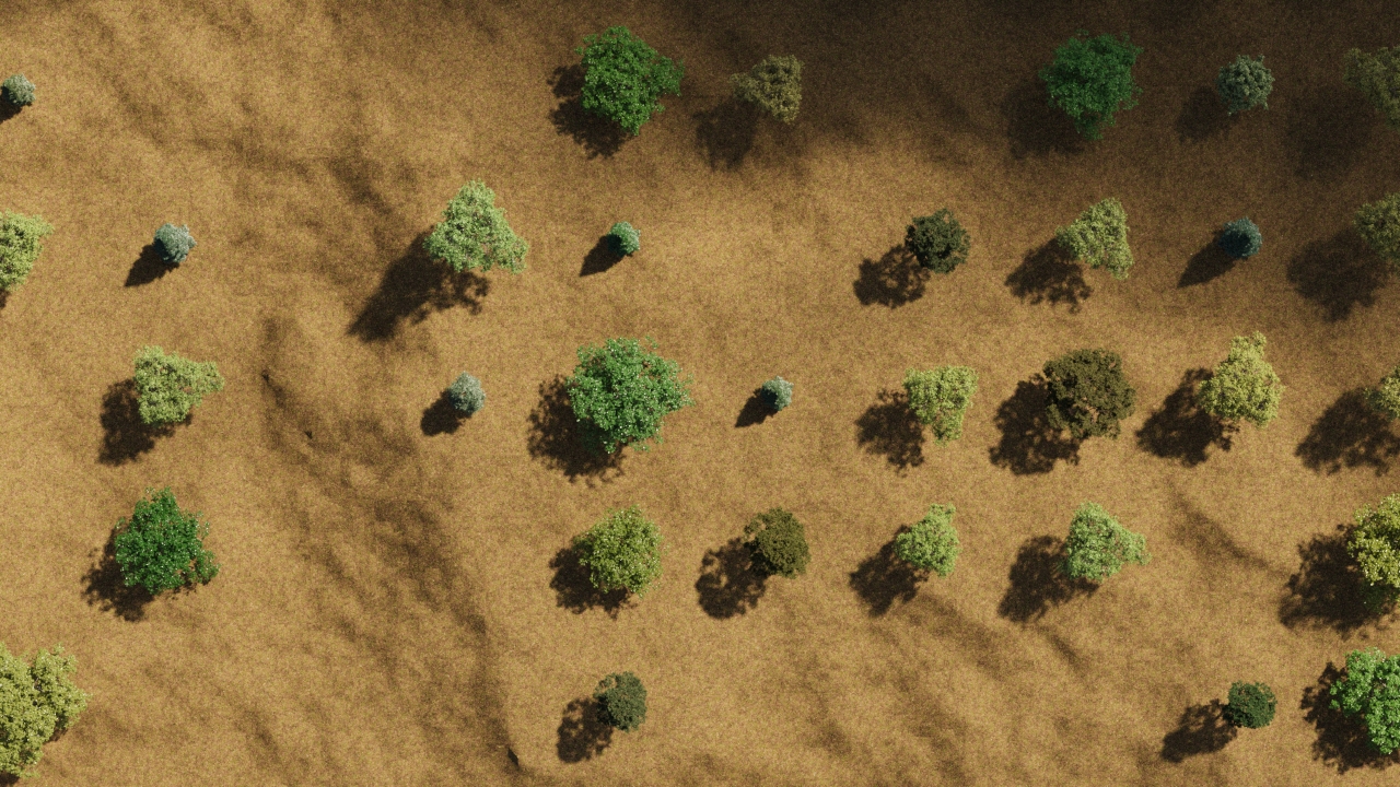
UV map distribution with Slope limitation from 0 to 20 degrees
The trees are distributed in a grid-like pattern and are only growing in the 0-20 degrees range.

Scattering with no altitude or slope limitations.
The trees are uniformly covering the surface.

Slope limitation from 0 to 45 degrees.
The trees are only growing in the 0-45 degrees range.
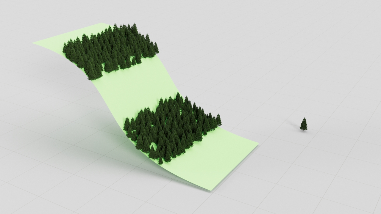
Slope limitation from 15 to 45 degrees.
The trees are growing only in the 15-45 degrees range.
Scattering with no altitude or slope limitations.
The trees are uniformly covering the surface.

Altitude limitation from 0 to 15 meters.
The trees are growing only in the 0-15 meters range.
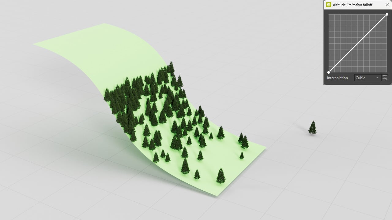
Altitude limitation from 0 to 15 meters. Falloff Curve resulting in less instances in the lower areas.
The trees are growing only in the 0-15 meters range. The curve makes the scattering less frequent in the lower areas.
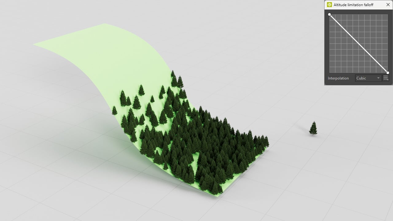
Altitude limitation from 0 to 15 meters. Falloff Curve resulting in less instances in the upper areas.
The trees are growing only in the 0-15 meters range. The curve makes the scattering less frequent in the higher areas.

Scattering on a torus. Slope limitation from 0 to 45 degrees.
The trees are growing only in the 0-45 degrees range.
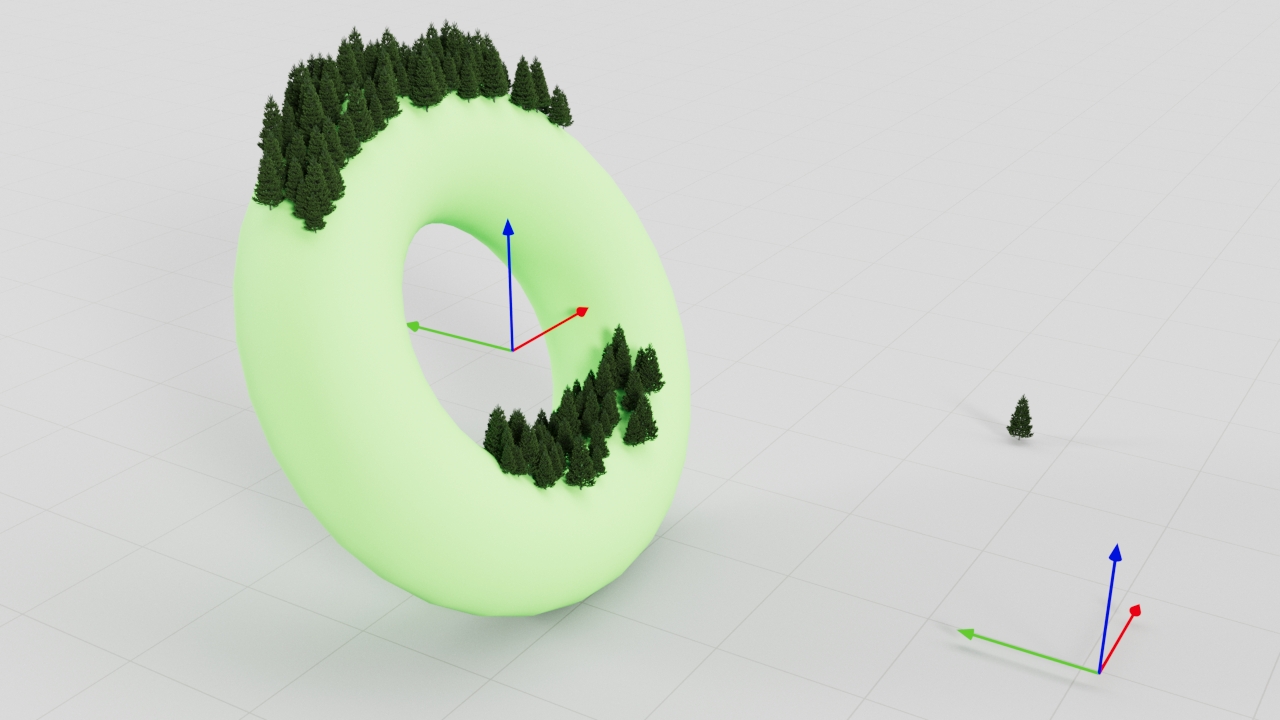
Scattering on a torus. The torus object is rotated. Slope limitation from 0 to 45 degrees. Mode set to "World".
The torus object is rotated. With the "World" mode enabled, the trees are growing only in the 0-45 degrees range calculated within the world coordinate system.

Scattering on a torus. The torus object is rotated. Slope limitation from 0 to 45 degrees. Mode set to "Local".
The torus object is rotated. With the "Local" mode enabled, the trees are growing only in the 0-45 degrees range calculated within the torus object's local coordinate system.

Altitude limitation from 0 to 15 meters.
The trees are growing in the 0-15 meters range.

Altitude limitation from 0 to 15 meters. The object is moved higher. "World" mode.
The distribute-on object is moved higher. With the "World" mode, the trees are growing in the 0-15 meters range calculated within the world space regardless of the distribute-on object's position.
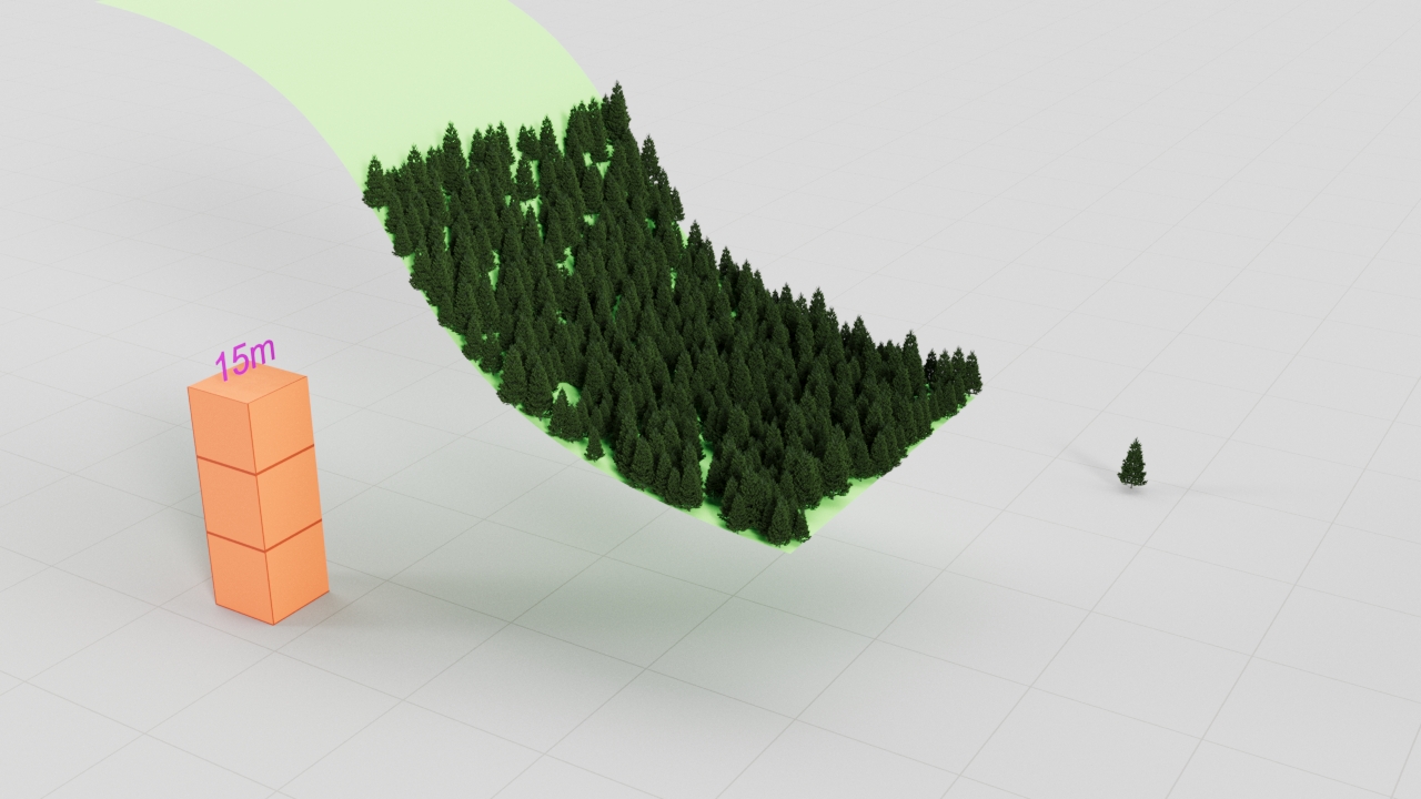
Altitude limitation from 0 to 15 meters. The object is moved higher. "Position Independent" mode.
The distribute-on object is moved higher. With the "Position Independent" mode, the trees are growing in the 0-15 meters range calculated within the distribute-on object's space.
Transformations
Translation
From - To – Specifies the translation range for X, Y, and Z axes, in world units.
Map – Specifies the texture map to use for translation.
Mode – Decides how the Map is interpreted to control the translation. RGB maps can be used to control translation in specific axes. Grayscale maps control translation proportionally in all axes.
Map fixed – Black areas of the map represent the From values. White areas represent the To values. Map areas with shades between black and white represent the values between From and To. No randomization occurs.
Random amount – No randomization occurs in black areas of the map. Full randomization occurs in white areas of the map. From and To values specify the lowest and highest translation allowed for the randomization.
Stepping distance – When nonzero, switches the random translation from a continuous to a discrete one, with steps specified by this parameter value. The From and To are still used as bounds. This effect is used only for the selected axes.
Rotation
From - To – Specifies the rotation range for X, Y, and Z axes, in degrees.
Map – Specifies the texture map to use for rotation.
Mode – Decides how the Map is interpreted to control the rotation. RGB maps can be used to control rotation in specific axes. Grayscale maps control rotation proportionally in all axes.
Map fixed – Black areas of the map represent the From values. White areas represent the To values. Map areas with shades between black and white represent the values between From and To. No randomization occurs.
Random amount – No randomization occurs in black areas of the map. Full randomization occurs in white areas of the map. From and To values specify the lowest and highest translation allowed for the randomization.
Stepping angle – When non-zero, switches the random rotation from a continuous to a discrete one, with steps specified by this parameter value. The From and To are still used as bounds. This effect is used only for the selected axes.
Normal vs. Z – Controls the alignment of instances to the surface normals. It blends the surface normal (value of 0) with +Z when the value is above 0, or with -Z when the value is below 0.
Preserve model rotation – When enabled, instances preserve the original rotation of their models (instanced objects). Otherwise, the original rotation is ignored.
Look At – When enabled, instances in a range get turned towards a specified direction.
Target object – Pick an object according to which the direction is calculated. When a geometry object is picked, each instance gets oriented towards the center of the object's bounding box. When a camera object is picked, each instance gets oriented towards the camera.
Look axis – Selects which of the object's axes gets turned towards the direction.
Reverse – When enabled, the reverse of the selected axis gets turned towards the direction.
Horizontal – When enabled, the selected look-at axis gets turned only within the plane which is perpendicular to the normal.
Falloff distance – Specified the range in which instances get affected by the look-at specifications. When non-zero, only the in-range instances get affected; otherwise, all the instances get affected. There is no effect when a sun object is picked. The way how the instances get affected is determined by the falloff curve.
Falloff Curve – Opens a falloff curve editor. The curve specifies how the strength of the look-at effect varies across the falloff distance. Lowering the point on the left side of the curve results in lowering the strength closer to the target. Lowering the point on the right side of the curve results in lowering the strength close to the falloff distance.
Scale
From - To – Specifies the scale range for X, Y, and Z axes, in percent.
Map – Specifies the texture map to use for scaling.
Mode – Decides how the Map is interpreted to control the scale. RGB maps can be used to control scale in specific axes. Grayscale maps control scale proportionally in all axes.
Map fixed – Black areas of the map represent the From values. White areas represent the To values. Map areas with shades between black and white represent the values between From and To. No randomization occurs.
Random amount – No randomization occurs in black areas of the map. Full randomization occurs in white areas of the map. From and To values specify the lowest and highest translation allowed for the randomization.
Legacy – From and To values decide about the overall randomization and are then multiplied by the values of the Map. This means that black areas of the map are always interpreted as zero scale.
Stepping percentage – When non-zero, switches the random scaling from a continuous to a discrete one, with steps specified by this parameter value. The From and To are still used as bounds. This effect is used only for the selected axes.
Uniform scale – When enabled, instances get scaled in all axes using the values for the X axis. When disabled, each axis uses independent values.
Preserve model scale – When enabled, instances preserve the original scale of their models (instanced objects). Otherwise, the original scale is ignored.

Examples: Transformations
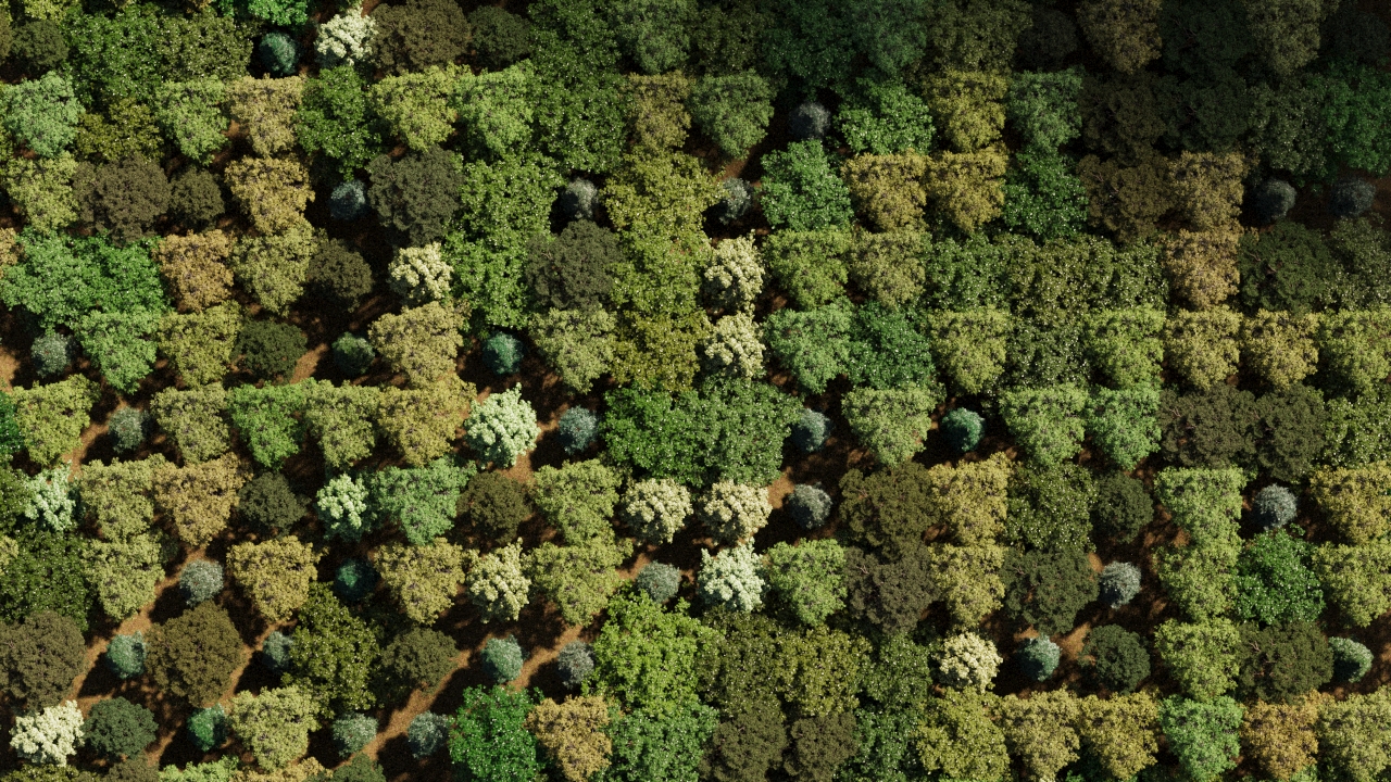
No randomization The positions, rotation, and scaling of the tree objects is not randomized.
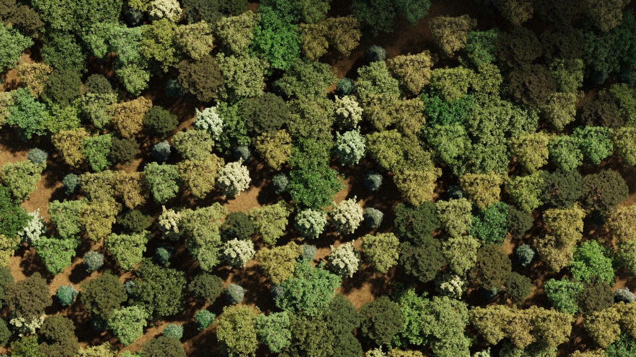
Randomized translation The trees are randomly translated.

Randomized rotation The trees are randomly rotated.

Randomized scale The trees are randomly scaled.
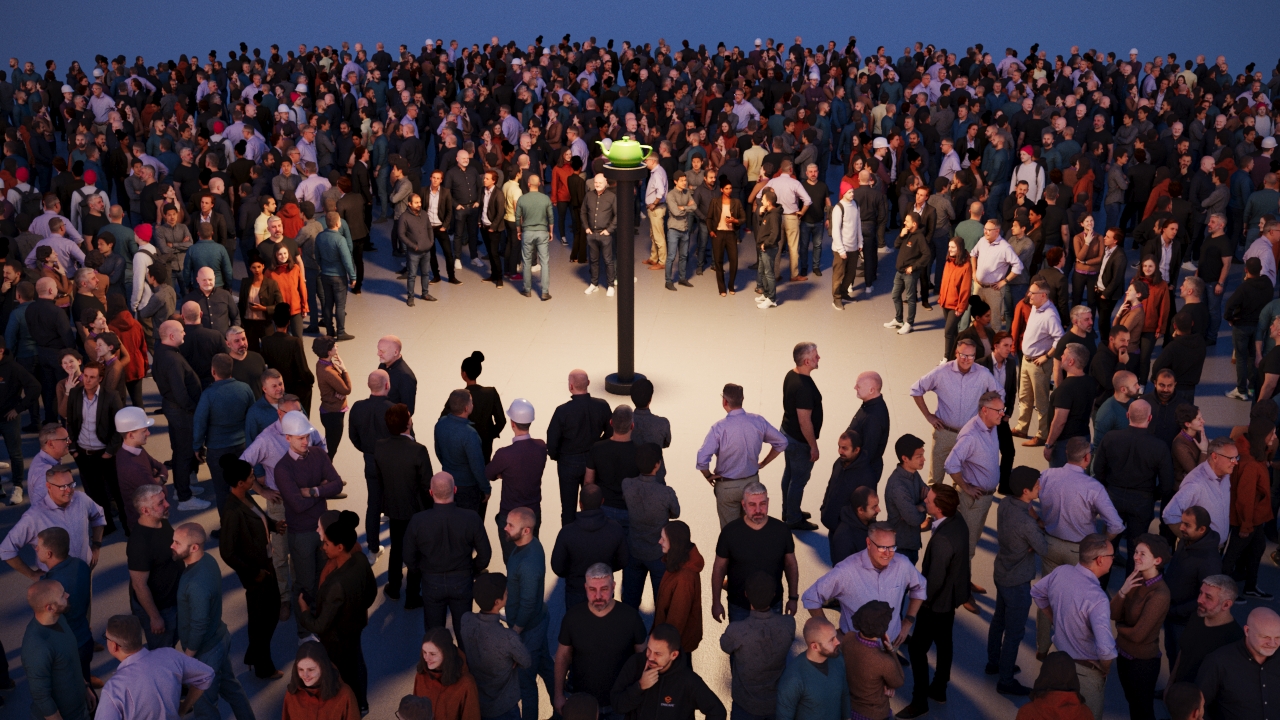
"Look at" disabled. With the "Look at" option disabled, the 3D people are facing random directions.

"Look at" enabled. Falloff distance set to 8 meters. With the look-at falloff distance set to 8 meters, any 3D people farther away than 8 meters from the teapot object are no longer affected by the "look at" effect and are rotated randomly.
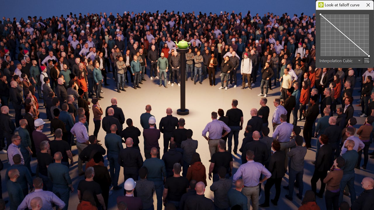
"Look at" enabled. Falloff distance set to 25 meters. Custom curve enabled. With the look-at falloff distance set to 25 meters and a custom falloff curve, there is a gradual transition from the people looking directly at the teapot (close to the teapot) to fully randomized rotation (25 meters from the teapot and farther away).
"Look at" disabled. With the "Look at" option disabled, the 3D people are facing random directions.

"Look at" enabled. With the "Look at" option enabled, all the 3D people are facing the teapot object.

"Look at" enabled. "Horizontal" option disabled. With the "Horizontal" option disabled, the 3D people are not only rotated horizontally towards the teapot, but all their rotation axes are affected making it look as if they were about to fall.

"Look at" enabled. "Reverse" option enabled. With the "Reverse" option enabled, the look-at direction is reversed.
Areas
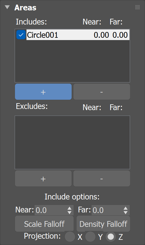
Includes – A list of splines or objects where the instances are allowed to be scattered.
Excludes – A list of splines or objects where the instances are not allowed to be scattered.
Include/Exclude options
Near - Far – Falloff distance from the selected object/spline projected to the selected axis plane up to which all instances get included or excluded, depending on the type of the object/spline. Scale and density of instances between the near and far falloffs change linearly - from 1.0 to 0.0 in case of inclusion, and contrariwise in case of exclusion.
Scale Falloff – Opens the curve editor, where the curve shapes how instance scale changes across the Near>Far range. Interpolation can be adjusted between Cubic and Linear.
Scale Falloff Curve Editor
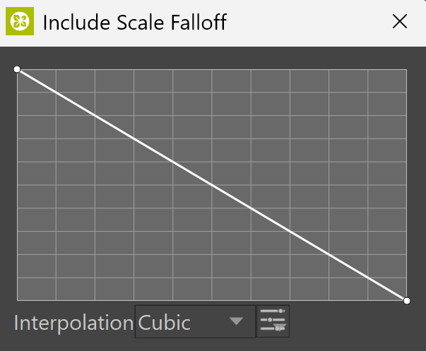
Density Falloff – Opens the curve editor, where the curve shapes how instance density changes across the Near>Far range. Interpolation can be adjusted between Cubic and Linear.
Density Falloff Curve Editor

Projection – Based on which axis to project the spline or object include/exclude areas.
Examples: Areas

Include (spline)

Exclude (spline)

Include (polygon)

Exclude (polygon)
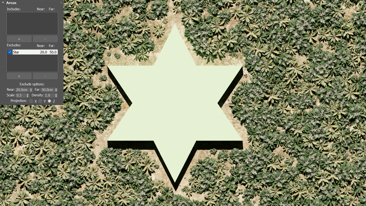
Exclude (polygon) - Near: 20m, Far: 50m
Examples: Scale Falloff

In this example circle spline is used as a Spline Exclude, with Near and Far defining the falloff distance around it.

When the Scale Falloff curve is lowered, the Instances stay smaller for longer across the range, fading down gradually and creating a softer, tapered edge.

When the Scale Falloff curve is raised, the Instances reach full size sooner toward the spline, creating a sharper, more defined edge.
Examples: Density Falloff

This example displays a default linear curve (Near 20 / Far 200). The Density falls off evenly across the range, giving a balanced transition at the spline edge.
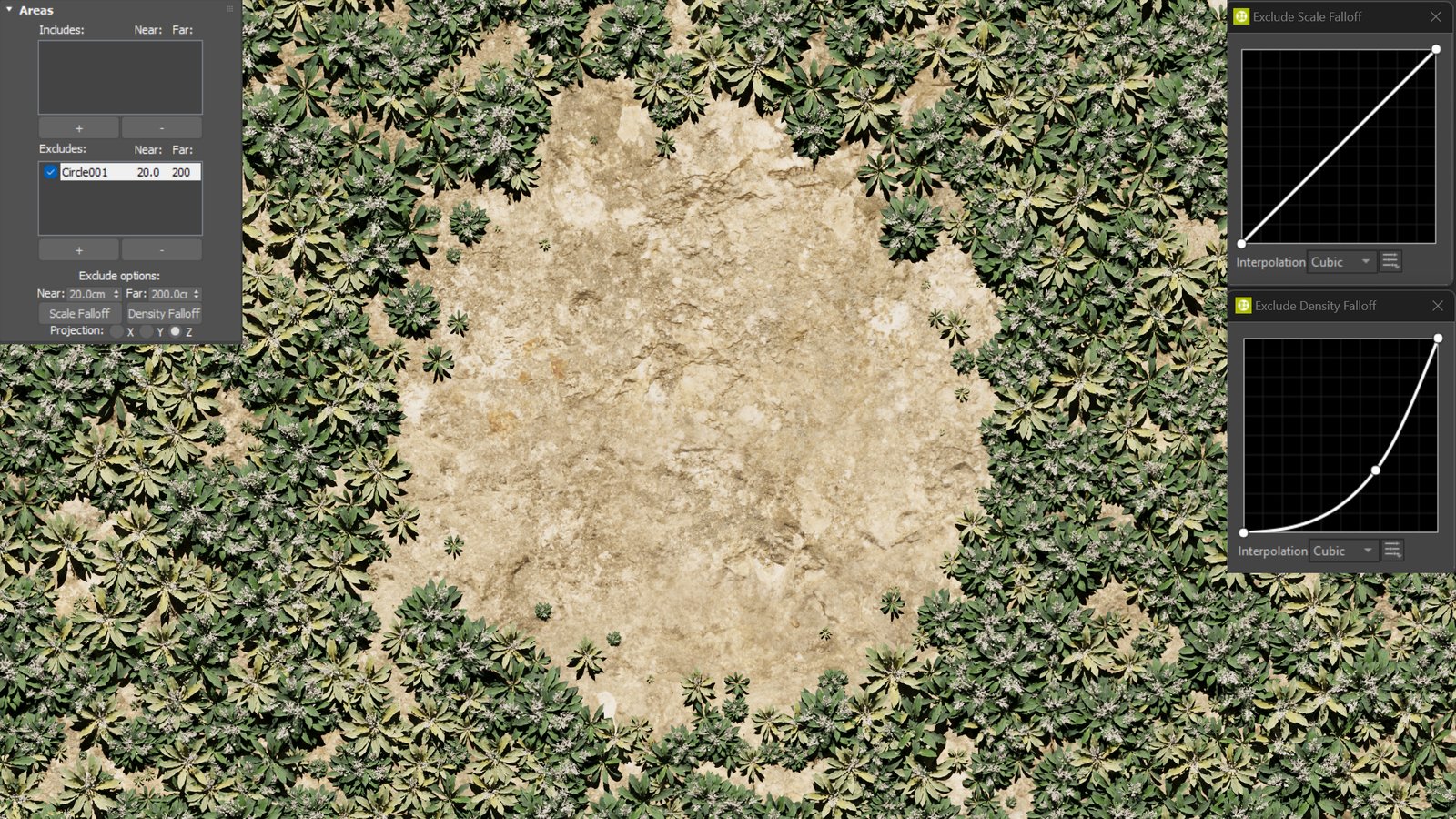
When the Density Falloff curve is lowered, the Instances thin out earlier in the range, widening the cleared area and creating a softer, more gradual edge.

When the Density Falloff curve raised, the Instances stay dense closer to the spline, tightening the cleared area and creating a sharper, more defined edge.
Spline Scattering
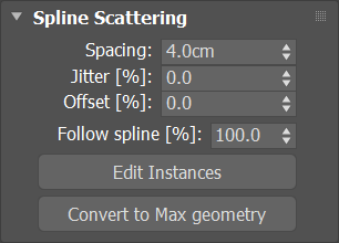
Spacing – Sets spacing between scattered instances measured in world units.
Jitter – Randomly jitters every instance along the spline. The value means how much of the Spacing (half on each side) can be used to jitter around original position of each instance, e.g. 200% means that every instance jitters by up to the entire Spacing on the left and the entire Spacing on the right.
Offset – Moves all scattered instances along the spline. The value means by how much of the Spacing the instances shall move, e.g. 100% moves the first instance by entire Spacing so that it appears instead of the second one, the second one instead of the third one, etc.
Follow spline – Controls how scattered instances get oriented along the spline. With default 100% instances follow the spline and are oriented along local tangent direction. For 0%, instance orientations are unchanged.
Edit Instances – Switches to Instances sub-object mode, allowing you to override individual instances in the viewport. You can move, rotate, scale, or delete them. It is not effective at a greater scale, but may serve well for final touches of small amount of instances.
Convert to Max geometry – Replicates this scatter using 3ds Max instances. This is usable only for a small number of objects.
Bounding Box Scattering
Count – Defines an exact number of instances to scatter - either overall, or per a volume in the case of scattering defined by density (Per cube). The number is always limited by the Max. limit.
Per cube – When enabled, the number of instances to scatter is defined by density (Count per cube having the given edge length). The number of instances is always limited by the Max. limit. The value specifies the edge length of the cube defining a volume for computing scattering density (Count, Per cube). The length is measured in world units.
Edit Instances – Switches to Instances sub-object mode, allowing you to override individual instances in the viewport. You can move, rotate, scale, or delete them. It is not effective in great scale, but may serve well for final touches of small amount of instances.
Convert to Max geometry – Replicates this scatter using 3ds Max instances. This is usable only for a small number of objects.

Info
Stats
Instances (editable instances):
Total– The total number of instances generated by the currently selected Scatter.
Scattered- The total number of instances procedurally generated by the currently selected Scatter.
Painted- The total number of instances generated by the currently selected Scatter with the Brush in the Edit Instances.
Objects- The total number of objects generated by the currently selected Scatter.
Polygons – The total number of polygons generated by the currently selected Scatter.
About Chaos Scatter – Shows the exact version of the currently installed Chaos Scatter plugin.

Chaos Scatter Maps
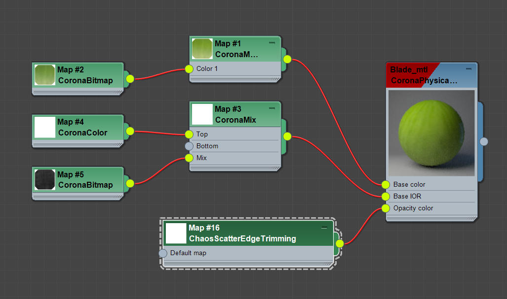
Edge Trimming Map
Default map – If a material is using some opacity texture in addition to the Edge Trimming map, this texture can be defined here.
Click here to see the UI Path


Examples: Edge Trimming Map

Edge trimming disabled
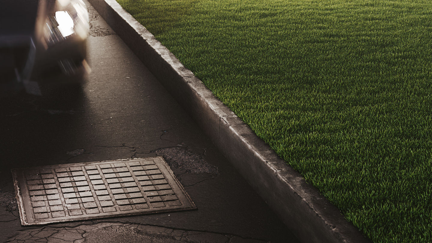
Edge trimming enabled
Click here to see the material setup
Surface Color Map
Source
Custom map – Uses a custom map as the surface color. You can then randomize this map's hue and gamma using the built-in controls.
Surface diffuse/base map – Automatically uses the distribute-on object's diffuse/base map.
Hue random – Controls randomization of the resulting color hue. The value specifies maximal distance from the original hue (in range of 0-100%) where 0% disables hue randomization and 100% applies maximal hue randomization.
Gamma random – Adds additional randomization of mid-tones (gamma) to the result (in a range of 0-100%), where 0% disables randomization and 100% applies maximal reasonable gamma randomization.
UI Path: Material Editor|| > Material/Map Browser > Maps > Chaos Scatter > ChaosScatterSurfaceColor


Examples: Surface Color Map

Scattering disabled

Scattering enabled
Click here to see the material setup
