V-Ray for Blender
Displacement
This page provides information about the Displacement node in V-Ray for Blender.
Last updated 27 March 2026
This page provides information about the Displacement node in V-Ray for Blender.
Overview
Displacement mapping is a technique for adding detail to your scene geometry without having to model it first. The concept is very similar to bump mapping. However, bump mapping is a shading effect that only changes the appearance of a surface, while displacement mapping actually modifies the surface.
The attributes in this section affect V-Ray displacement and can be added to any polygonal mesh object.
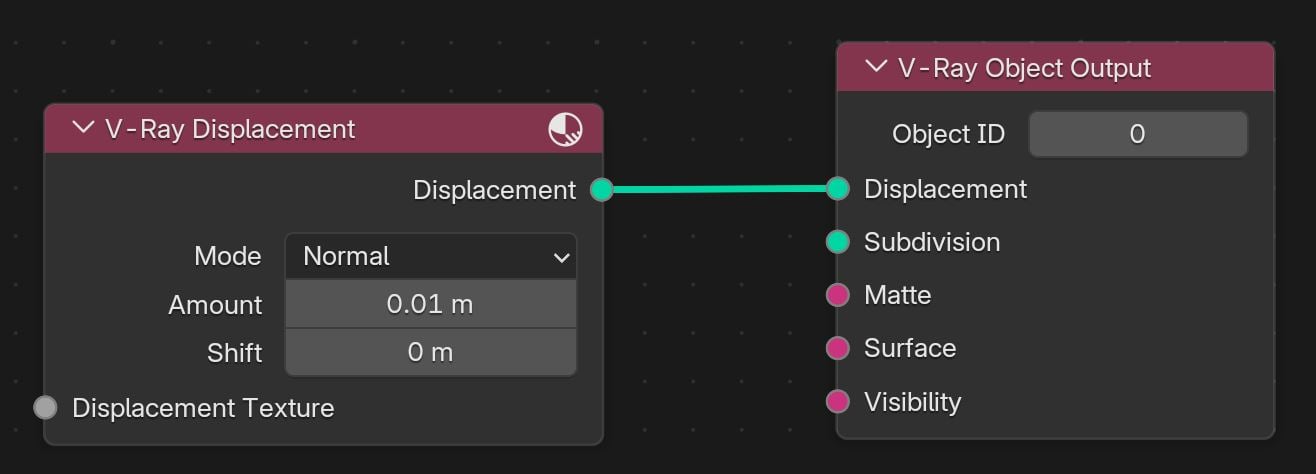
UI Path: ||V-Ray Node Editor|| > Object > Add > Geometry > V-Ray Displacement
Node Input Sockets
Displacement Texture – Allows you to connect a black-and-white displacement texture. See the example.

Displacement
Mode – Specifies the displacement generation mode:
Normal – Takes the original surface geometry and subdivides its triangles into smaller sub-triangles which are then displaced. It can be applied for arbitrary displacement maps with any kind of mapping.
2D – Bases the displacement on a texture map that is known in advance. The displaced surface is rendered as a warped height field based on that texture map. The actual raytracing of the displaced surface is done in texture space, and the result is mapped back into 3D space. The advantage of this method is that it preserves all the details in the displacement map. However, it requires that the object has valid texture coordinates. You cannot use this method for 3D procedural textures or other textures that use object or world coordinates. The displacement map can take any value.
Vector – If using a displacement texture that is not grayscale, V-Ray converts it to grayscale before rendering the displaced geometry. This mode allows V-Ray to use the Red, Green, and Blue channels of the displacement texture to displace the geometry in the U and V directions in addition to the direction of the face normal.
Vector (Absolute) – A vector-type displacement mode in which the texture is interpreted as a 0.5-based tangent space displacement map.
Vector (Object) – The texture values represent 0-based displacement in object space. Recommended when a VRayPtex texture is used for displacement. If mesh information is stored in the Ptex file, V-Ray can also displace correctly mesh deformations.
Amount – The amount of displacement. A value of 0.0 means the object appears unchanged. Higher values produce a greater displacement effect. This can also be negative, in which case the displacement pushes geometry inside the object.
Shift – Specifies a constant which is added to the displacement map values, effectively shifting the displaced surface up and down along the normals. This can either be positive or negative. For more information, see the Displacement Shift example.
Advanced
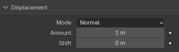
Geometry Generation – Determines when the geometry is compiled during rendering. Note that when rendering with V-Ray GPU, all geometry is pre-compiled.
Pre-tessellated – The subdivision geometry is pre-compiled into an acceleration structure at the beginning of the rendering and remains there until the end of the frame. This can speed up the rendering and increase memory usage.
On the Fly – The subdivision geometry dynamically goes into the dynamic memory pool during rendering, from which it can later be removed, if needed. This process is at the expense of some speed but potentially saves memory.
Keep Continuity – When enabled, V-Ray tries to produce a connected surface. Use it when you get splits (usually around sharp edges) in the displaced geometry. For more information, see the Keep Continuity example .
Cache Normals – When enabled, V-Ray generates and saves information about the normal of each newly generated vertex. This requires additional memory but speeds up the shading calculations during rendering.
Use Water Level – When enabled, this clips the surface geometry in places where the displacement map value is below the threshold specified by the Water Level field.
Water Level – Geometry that is at a height under this value is clipped from the displacement.
Use Bounds – When enabled, the min/max values for the displacement texture are specified by the Min Bound and Max Bound parameters. Otherwise, these are calculated automatically. This parameter is not available for the 2D Mode.
Min Bound/ Max Bound Float – The lowest and highest values for the displacement texture. These thresholds take the Value property from their assigned colors. Nodes can also be connected to determine the bounds.
2D Displacement
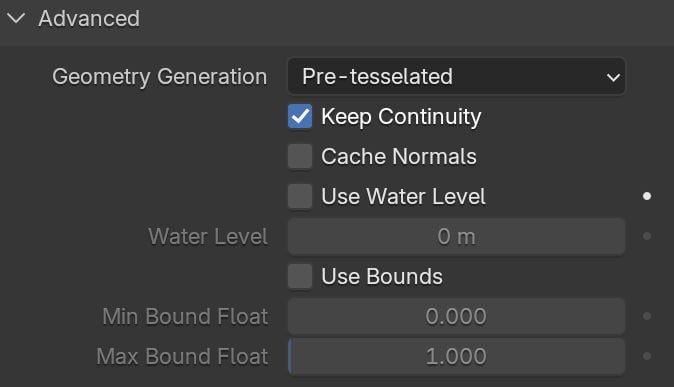
Resolution – Determines the resolution of the displacement texture used by V-Ray. If the texture map is a bitmap, it would be best to match this resolution to the size of the bitmap. For procedural 2D maps, the resolution is determined by the desired quality and detail in the displacement. Note that V-Ray also automatically generates a normals map based on the displacement map, to compensate for details not captured by the actual displaced surface.
Filter Texture – When enabled, the texture map is filtered before the actual displacement takes place.
Filter Blur – Specifies the amount of blur that is applied to the texture before the displacement takes place. This parameter is not available for the Normal Mode.
Precision – Related to the curvature of the displaced surface. Flat surfaces can do with a lower precision (for a perfectly flat plane, you can use 1), more curved surfaces require higher values. If the precision is not high enough you can get dark spots ("surface acne") on the displacement. Lower values compute faster.
Tight Bounds – When enabled, V-Ray tries to compute the exact bounding volume of the displaced triangles from the original mesh. This requires presampling of the displacement texture, but the rendering is faster if the texture has large black or white areas. However, if the displacement texture is slow to evaluate and varies a lot between full black and white, it may be faster to turn this option off. When it is off, V-Ray assumes worst-case bounding volumes and does not pre-sample the texture. This parameter is active only when the Use Global Settings parameter is disabled.
Displace 2d Multi Tile – When enabled, 2D Displacement can work with tiled textures (UVTILE/UDIM).
Quality Overrides
Use Global Settings – When enabled, the global displacement quality settings are used. The Edge Length, Max Subdivision, View Dependent, and Tight Bounds options are derived from the Globals tab of the Render Settings.
View Dependent – Specifies whether Edge length is expressed in pixels or world units. When this option is enabled, the Edge length value determines the maximum length of a subtriangle edge in pixels, and a value of 1.0 means that the longest edge of each subtriangle is about one pixel long when projected on the screen. When this option is disabled, Edge length is the maximum subtriangle edge length in world units. This parameter is active only when the Use Global Settings parameter is disabled.
Edge Length – If Use Global Settings is disabled, this parameter determines the approximate edge length for the sub-triangles. This affects the degree of subdivision before displacement, which in turn affects the quality of the displacement itself. Each triangle of the original mesh is subdivided into a number of sub-triangles. More triangles mean more detail in the displacement, slower rendering times, and more memory usage. Less subtriangles mean less detail, faster rendering, and less memory used. Units used for this parameter depend on the View Dependent parameter. For a preview, see the Edge Length example.
Max Subdivisions – Controls the maximum sub-triangles generated from any triangle of the original mesh when the Use Global Settings parameter is disabled. The value is, in fact, the square root of the maximum number of subtriangles. For example, a value of 256 means that, at most, 256 x 256 = 65536 subtriangles are generated for any given original triangle. It is not a good idea to keep this value very high. If you need to use higher values, it is better to tessellate the original mesh itself into smaller triangles instead. The actual subdivisions for a triangle are rounded up to the nearest power of two (this makes it easier to avoid gaps because of different tessellations on neighboring triangles).

Example: Displacement Shift
Note that the Shift parameter is an absolute value in world units. If you change the Displacement Amount, you will probably need to adjust the Displacement Shift too. In this example, the Displacement Amount is 1 and the Water Level is -30 (the water level needs to exceed the displacement shift). The displacement is defined by a V-Ray Noise texture with a Size of 0.025 to create subtle waves.
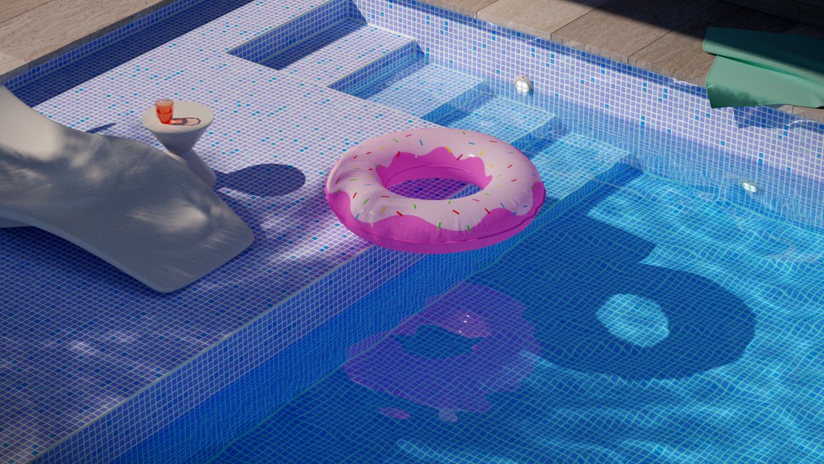
Shift = -20.0

Shift = 0.0

Shift = 10.0
Example: Keep Continuity
The Keep Continuity option is useful for objects with disjoint normals on neighboring triangles, usually because of different smoothing groups. In the middle image you can see the edge splits produced by disjoint normals. Using the Keep Continuity option avoids this problem. This option also helps to produce a smoother result across material ID boundaries for objects that have been assigned Multi-Sub-Object materials.

No displacement

Keep continuity = disabled
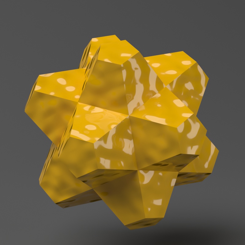
Keep continuity = enabled
Example: Edge Length
This example shows the effects of increasing the Edge Length parameter. In this example, View Dependent is enabled, so Edge Length is expressed in pixels. In the examples, the closeup view is a blow-up rather than a zoomed view. This means that Edge Length in the closeup view refers to pixels in the original image, not the blow-up rendering. Click the images for a larger view.

Edge length = 0.5

Edge length = 5.0
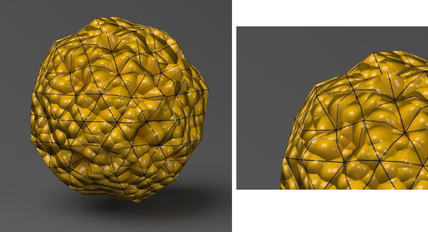
Edge length = 10.0
Example: Texture
In this example, a texture file is used to determine the displacement pattern. V-Ray Bitmap is used to import the file. The image needs to be black and white to serve as a correct reference for displacement. For clean borders, you need to make the image in the shape of your object. Expand the Node Editor Setup to view how the texture is shaped for this example. You can see the full process of applying this texture and tweaking its properties in the How to Add Displacement tutorial.

Before Displacement

After Displacement
Click on the images to view them in full size

V-Ray Node Editor setup