V-Ray for Cinema 4D
Sampler Info RE
This page provides information about the Sampler Info Render Element in V-Ray for Cinema 4D.
Last updated 19 September 2025
This page provides information about the Sampler Info Render Element in V-Ray for Cinema 4D.
Overview
The Sampler Info Render Element is a color image that provides information about the scene, with the choice to show any of various aspects as color blocks. This render element provides information about various aspects of the shaded points such as position, normal, bump normal, reflection/refraction vectors and UVW coordinates, which previously were only available through the Extra Texture Render Element. This render element can be used either for world position passes or normal passes. It extracts particular information about the scene, converting the gathered information into RGB data for use in compositing.

How to add a render element to a scene.

Properties
Type – Controls the type of render element produced by the Sampler Info element:
- Point – The X, Y, and Z coordinates of the point are converted to RGB data according to the Coordinate System that is set. This outputs a Position Pass for use in compositing.
- Normal vecNormal vector with bump mappingtor – The direction of the normal at the particular shaded point, according to which the Coordinate System is set.
- Reflection vector – Commonly used for adjusting reflections in the composite.✓
- Refraction vector – Commonly used for adjusting refractions in the composite.
- UVW coordinates – Extracts the UVW coordinates of the object at the particular shaded point. This can be used to apply another texture at a composite level.
- Normal vector with bump mapping – Produces the bump normal, according to the Coordinate System that is set.
- Backward occlusion – The red and green components of this render element represent the screen position of the shaded point at the beginning of the motion-blurred frame, while the blue component represents camera occlusion at the beginning of the motion-blurred frame. This can be used for denoising and/or post-process motion blur.
- Forward occlusion – The red and green components of this type represent the screen position of the shaded point at the end of the motion-blurred frame, while the blue component represents camera occlusion at the end of the motion-blurred frame. This can be used for denoising and/or post-process motion blur.
- Integer ID from node user attribute – Extracts any integer node user property into an integer render element. Can be used as an extended Object ID. Supports both V-Ray and Mograph user attributes.
- Float number from node user attribute – Extracts any floating-point node user property into a single-channel floating-point render element. Can be used to extract additional masks. Supports both V-Ray and Mograph user attributes.
- Color from node user attribute – Extracts any color node user property into a color render element. Can be used for masking in post-production. Supports both V-Ray and Mograph user attributes.
- Face index in mesh – Correlates points between separate bakings of the same mesh.
- Barycentric coordinates from face – Displays the Barycentric coordinates of the rendered objects.
- Tangent vector in object space – Displays tangent vector according to the object space.
- Bitangent vector in object space – Displays bitangent vector according to the object space
Point Multiplier – Acts as a multiplier when Type is set to Point.
Refraction IOR – Sets the index of refraction when the Type is set to Refraction vector.
Coordinate system – Determines the coordinate system used:
World – X, Y, and Z coordinates (in world space) of the point are converted to RGB data.
Object – X, Y, and Z coordinates (in object space) of the point are converted to RGB data.
Camera – X, Y, and Z coordinates (in camera space) of the point are converted to RGB data.
Relative – X, Y, and Z coordinates in the object space of the Relative Node are converted to RGB data.
Output – Controls the way data is stored in the render element. Available for all vector Types and face Types.
Vector – Values are stored directly without modification, including negative components.
Color – Values are scaled down by 0.5 and offset by 0.5 so that (0, 0, 0) maps to (0.5, 0.5, 0.5), (-1, -1, -1) maps to (0, 0, 0) and (1,1,1) maps to (1,1,1). This avoids negative values which might be necessary for some compositing packages.
UVW Channel – The UVW mapping channel used when the Type is set to UVW coordinates, Tangent / Bitangent vector in object space, if no UVW Channel Name is specified.
UVW Channel Name – The default UVW mapping channel used when the Type is set to UVW coordinates. Specifies the UVW Channel to render by the name of the UV set.
UVW Mode – Specifies what happens to UVW values outside the 0.0-1.0 range of the unit texture square:
Normal – Stores the UVW coordinates without modification.
Clamp – UVW coordinates above 1.0 are clamped to 1.0, and values below 0.0 are clamped to 0.0.
Tile – Wraps the UVW coordinates to the unit texture square.
Occlusion Bias – Controls the positional bias of the Backward occlusion and Forward occlusion types in order to prevent incorrect self-occlusion.
User Attribute – Determines which user attribute to connect to when a user attribute Type is selected..
Enable Deep Output – Specifies whether to include this render element in deep images.
Filtering – Applies an image filter to this channel. This option is not available for the user attribute Types and the Face index in mesh Type.
Denoise – Enables the render element's denoising, provided the Denoiser is enabled. This option is not available for the user attribute Types and the Face index in mesh Type.

Common Use
The V-Ray Sampler Info render element extracts particular information about the scene. It then converts the gathered information into RGB data that can be used for compositing. Here are examples of the types of data that can be extracted, and how that data is displayed in the render element.
The following examples have the coordinates system set to world space.

Point Type in World Coordinates
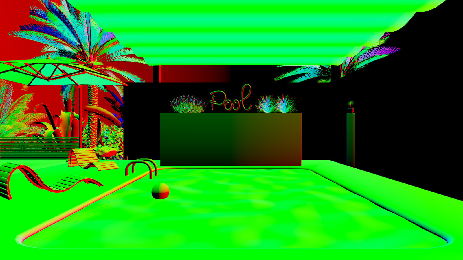
Normal vector Type in World Coordinates

Reflection vector Type in World Coordinates

Refraction vector Type in World Coordinates
Supported UVW Coordinate Types
These tables show the Pass Types within the Sampler Info Render Element and their render engine support.
Pass Type | Coord. System | UVW Mode | Output | V-Ray CPU | V-Ray GPU |
|---|
Pass Type | Coord. System | UVW Mode | Output | V-Ray CPU | V-Ray GPU |
|---|---|---|---|---|---|
Point | World | ✓ | ✓ | ||
Point | Object | ✓ | - | ||
Point | Camera | ✓ | ✓ | ||
Point | Relative | ✓ | - | ||
Normal vector | World | Vector | ✓ | ✓ | |
Normal vector | World | Color | ✓ | - | |
Normal vector | Object | Vector | ✓ | - | |
Normal vector | Object | Color | ✓ | - | |
Normal vector | Camera | Vector | ✓ | ✓ | |
Normal vector | Camera | Color | ✓ | - | |
Normal vector | Relative | Vector | ✓ | - | |
Normal vector | Relative | Color | ✓ | - | |
Reflection vector | World | Vector | ✓ | - | |
Reflection vector | World | Color | ✓ | - | |
Reflection vector | Object | Vector | ✓ | - | |
Reflection vector | Object | Color | ✓ | - | |
Reflection vector | Camera | Vector | ✓ | - | |
Reflection vector | Camera | Color | ✓ | - | |
Reflection vector | Relative | Vector | ✓ | - | |
Reflection vector | Relative | Color | ✓ | - | |
Refraction vector | World | Vector | ✓ | - | |
Refraction vector | World | Color | ✓ | - | |
Refraction vector | Object | Vector | ✓ | - | |
Refraction vector | Object | Color | ✓ | - | |
Refraction vector | Camera | Vector | ✓ | - | |
Refraction vector | Camera | Color | ✓ | - | |
Refraction vector | Relative | Vector | ✓ | - | |
Refraction vector | Relative | Color | ✓ | - |
Pass Type | Coord. System | UVW Mode | Output | V-Ray CPU | V-Ray GPU |
|---|
Pass Type | Coord. System | UVW Mode | Output | V-Ray CPU | V-Ray GPU |
|---|---|---|---|---|---|
UVW Coordinates | Normal | ✓ | ✓ | ||
UVW Coordinates | Clamp | ✓ | - | ||
UVW Coordinates | Tile | ✓ | - | ||
Normal vector with bump mapping | World | Vector | ✓ | - | |
Normal vector with bump mapping | World | Color | ✓ | - | |
Normal vector with bump mapping | Object | Vector | ✓ | - | |
Normal vector with bump mapping | Object | Color | ✓ | - | |
Normal vector with bump mapping | Camera | Vector | ✓ | - | |
Normal vector with bump mapping | Camera | Color | ✓ | - | |
Normal vector with bump mapping | Relative | Vector | ✓ | - | |
Normal vector with bump mapping | Relative | Color | ✓ | - | |
Backward occlusion | ✓ | - | |||
Forward occlusion | ✓ | - | |||
Integer ID from node user attribute | ✓ | ✓ | |||
Float number from node user attribute | ✓ | ✓ | |||
Color from node user attribute | ✓ | - | |||
Face index in mesh | Vector | ✓ | - | ||
Face index in mesh | Color | ✓ | - | ||
Barycentric coordinates from face | Vector | ✓ | ✓ | ||
Barycentric coordinates from face | Color | ✓ | - | ||
Tangent vector in object space | Vector | ✓ | ✓ | ||
Tangent vector in object space | Color | ✓ | - | ||
Bitangent vector in object space | Vector | ✓ | ✓ | ||
Bitangent vector in object space | Color | ✓ | - |
Notes
- When included in a multichannel EXR, the Sampler Info render element is always saved with lossless compression.