V-Ray for Maya
Rendering
This page provides general information about the Rendering tab of the V-Ray Volumetric Grid.
Last updated 19 September 2025
This page provides general information about the Rendering tab of the V-Ray Volumetric Grid.
Overview
For convenience, the shading and rendering of Volumetric effects (Render Mode: Volumetric, Volumetric Geometry, and Volumetric Heat Haze) are handled by the built-in Volumetric shader of the V-Ray Volume Grid. All parameters necessary for rendering a Fire / Smoke simulation can be found under the Rendering roll-out and its sub-rollouts.
The Volume Grid is able to operate in multiple rendering modes that can be divided into two main branches: volumetric and surfaces (Isosurface, Mesh, Ocean Mesh and Cap Mesh). The volumetric modes are used for fire and smoke. Maya materials can't be used to shade volumetrics, so their shading is described in the Fire , Smoke Color and Smoke Opacity roll-outs. The surface modes can be used for some interesting fire-related effects, like freezing flame or cartoon-style smoke. Unlike the volumetric modes, surface modes have no dedicated shader; they use the material applied to the Volume Grid.
The V-Ray Volume Grid also provides you with the option to generate a mesh surface based on any of the supported channels. Thus, a Smoke simulation can be rendered as a polygon mesh with a custom material applied to it.
Parameters
Enable Rendering | render – Enables/disables the rendering of the Volume Grid.
Render Presets... – Opens a menu for loading and saving different presets. The following options are available:
- Default Phoenix FD Render Settings
- Fire/Smoke from FumeFX
- Fire/Smoke .vdb from Houdini
- Liquid .vdb from Houdini
- Fire/Smoke .vdb from Maya Fluids
Render Mode | rendMode – Specifies the method for visualizing the grid content. For fire/smoke, you will want to select a Volumetric method. For liquids, select a geometry method.
Volumetric – Visualizes the content similar to a VRayEnvironmentFog. This method is used mostly for fire and smoke.
Volumetric Geometry – Used to export deep images and render elements such as normals, velocity, multi matte, etc. It produces the same result as the Volumetric option by using procedural geometry made up of multiple transparent layers. Note that the Approximate and Approximate+Shadows options for the Scattering parameter in the Smoke Color tab are not supported in this mode.
Volumetric Heat Haze – Produces the same result as the Volumetric option, but adds a heat haze effect when used with the Heathaze parameter. Note that you might need to increase the Max depth of a VRayMtl with refraction in case it intersects with the Heat Haze shader.
Isosurface – Used mostly for liquid simulations. It produces a procedural Isosurface geometry using the Surface section options. Compared to the Mesh mode, the result is always smooth but will take longer to render.
Mesh – The content is converted into a standard Maya mesh using the Surface section options. This mode is mostly used for liquids but can be applied to thick smoke using a scattering material or to plumes of smoke to create effects such as large underwater bubbles.
Ocean Mesh – The grid content is extended to a flat area, fitting the camera's view. In most cases, this mode is used with a displacement texture such as the Phoenix FD Ocean Texture.
Cap Mesh – Only the upper liquid surface is rendered. This mode can be used for swimming pools and other placid liquid surfaces.
Step (%) | rendStep – Specifies the ray marching step of the camera rays as a percentage of the cell size. As the renderer traces rays through the Volume Grid, this value controls how often to get information from the grid. If this value is more than 100, some cells start getting skipped and artifacts can result. If rendering volumetrics with a specific transparency curve, a lower percentage might be necessary so that fine details are not lost. On the other hand, increasing this value increases the rendering speed. This parameter is used when Mode is set to Volumetric, Volumetric Geometry, Volumetric Heat Haze and Isosurface modes. See the Step % example below.
Shadow Step (%) | shadowStep – Specifies the ray marching step of the rays used to evaluate the lighting (shadow rays) as a percentage of the cell size. Usually, this value can be higher than Step %, as generally, shadows do not need so much detail. Increasing the Shadow Step % also speeds up rendering performance, particularly with dome and area lights.
Border Fade (units) | borderOpacityFade – Makes the content near the grid's boundaries more transparent to prevent sharp edges from being rendered. This parameter controls how far from the boundaries the transparent effect should start, in scene units.
Sampler Type | rendSamplerType – Determines the blending method between adjacent grid cells.
Box – Displays cells as cubes. There is no blending between neighbor cells. This is the fastest mode.
Linear – Linear blending occurs between neighbor cells to smooth out the fluid's look. Sometimes this mode may unveil the grid-like structure of the fluid. Up to 20-30% faster than the Spherical option.
Spherical – Uses special weight-based sampling for the smoothest looking fluid. With increasing resolution, the visual advantage of this method over the Linear method becomes less noticeable.
Motion Blur Multiplier | rendVelMult – Specifies a multiplier that affects the strength of the motion blur. May also be a negative value.
Volumetric Motion Blur | volMoblurMethod – Specifies the type of Motion Blur that will be used.
Ray-traced – The default Volumetric Motion Blur method.
Grid-based – This method could be used instead of the default Ray-traced method in cases when you need more visible motion blur streaks, especially with faster moving fluids. The method requires a pre-pass and uses more memory.
Velocity Texture | rendVelTexture – Specifies a custom texture used for motion blur when rendering Fire/Smoke simulations. The colors of the texture represent the velocity direction for each cell, similar to how Vector Displacement textures are evaluated. Every simulator cell receives a certain color from the texture, treats it as a direction vector and stretches the contents of the simulator along to produce motion blur. This parameter can be used with a V-Ray User Color texture for motion blur in a single direction(e.g. by setting the color to (0, 1, 0) for motion blur in the +Z axis), or any other Maya texture applied as a 3D projection. The texture overrides the Velocity grid channel even if available in the cache files. Note that the Y and Z components of the velocity vectors are flipped - they are sampled respectively from the Blue and Green color values of the texture.
UVW Bias | rendUVWBias – Offsets the UVW channel's sampling position along the direction of the normal.

Example: Step %
This example shows how the Step % value can be used to improve the quality of the ray-marching.

Step %: 50

Step %: 150
Example: Heat Haze
This example shows how Heat Haze adds refraction at each ray-marching step through the volume. This only affects the camera's view. Heat haze will not affect shadows cast through a volume.

Heat haze: 0

Heat haze: 1
Example: Volumetric Motion Blur for Fire

Grid-based Volumetric Motion Blur

Ray-traced Volumetric Motion Blur

No Volumetric Motion Blur
Example: Volumetric Motion Blur for Explosions

Grid-based Volumetric Motion Blur
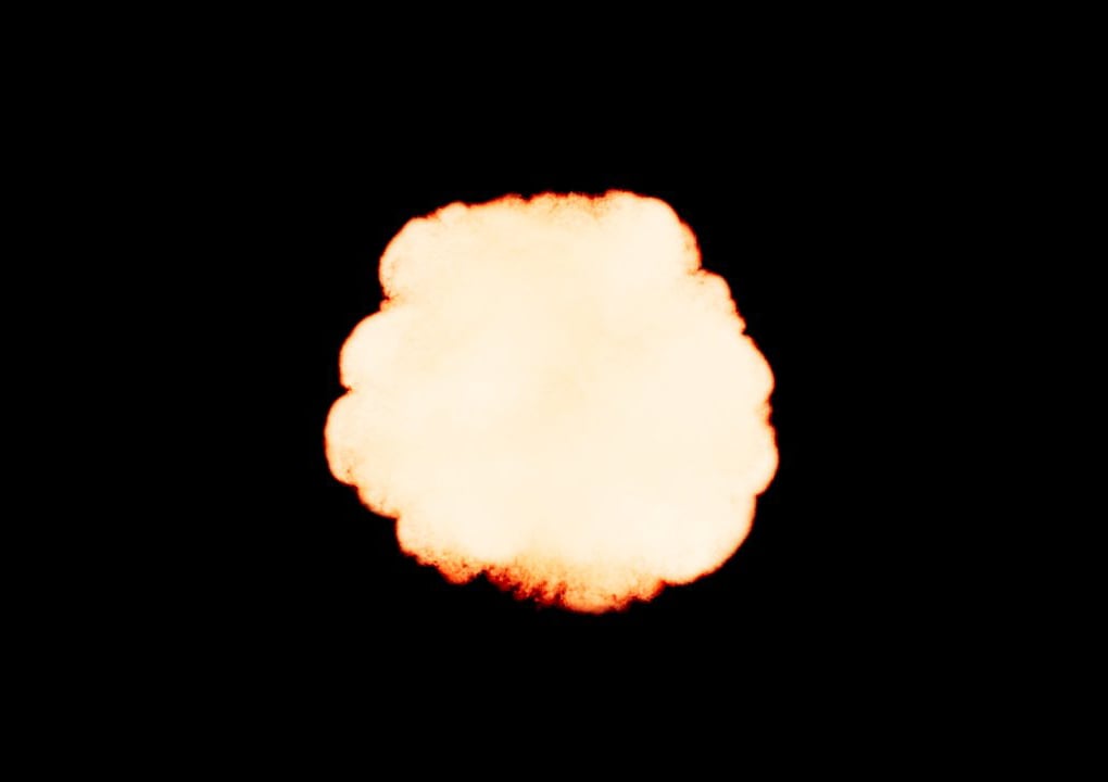
Ray-traced Volumetric Motion Blur

No Volumetric Motion Blur
Surface
This section controls the conversion of the grid content into geometry. If Render Mode is set to Mesh, Ocean Mesh, Cap Mesh or Isosurface, the Surface channel needs to be set and an appropriate Isosurface Level must be chosen from this section.
The controls in this section also denote the surface used in Gradient and Surface-driven displacement. This way it can affect all render modes, not just the surface modes.
The technique for generating the surface is based on the isosurface concept. The resulting surfaces are mostly used to render liquids, but can be used for smoke and fire as well to create effects like underwater bubbles, freezing fire, etc.
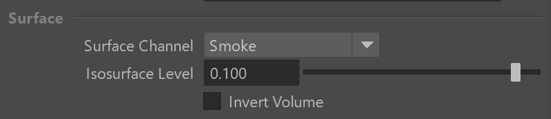
Surface Channel | sarg – Specifies the channel that defines the surface of the fluid. It is used for solid rendering and displacement.
Texture - the values of a custom texture will define the liquid surface.
Liquid/Temperature - the Liquid/Temperature channel will define the liquid surface. Temperature is typically in the range 0-1 for Liquid simulations and 600-2000 for Fire / Smoke simulations.
Smoke - the Smoke channel will define the liquid surface. Smoke is typically in the range of 0-1 for Fire / Smoke simulations.
Speed - the Speed channel will define the liquid surface. Speed channel output has to be enabled for this to work. Speed is calculated as the length of the velocity vector for each voxel.
Fuel - the Fuel channel will define the liquid surface. Fuel channel output has to be enabled for this to work.
Texture | rendEffectTex – If the Surface Channel is set to Texture, this slot specifies the texture. In Mesh, Ocean Mesh, Cap Mesh and Isosurface render modes, the selected map will completely replace the cache files that have been loaded, if any.
Isosurface Level | rendSurfLevel_x, rendSurfLevel_t, rendSurfLevel_s, rendSurfLevel_v, rendSurfLevel_f – Allows you to specify a threshold value for the generation of the geometry surface. Grid cells below this value are ignored. Isosurface Level is used only in Isosurface, Mesh, Ocean Mesh and Cap Mesh Modes.
Invert Volume | rendInvertNorm – By default the values above the surface level are considered internal. When enabled, this option swaps the inside and outside.


Render Cutter
Use Render Cutter | rendUseGizmo – When enabled, rendering will occur only inside the selected geometric object's volume. If Fire Lights are enabled, only those inside the cutter will be rendered. Note that this will not work when the Render Mode is set to Volumetric Geometry.
Set Selected Object as Render Cutter – When a polygon mesh and the Volume Grid are selected, the selected mesh is used as the render cutter for the geometry generated by the Volume Grid.
Invert Cutter | rendInvGizmo – When enabled, rendering occurs only outside of the render cutter. This is not the same as a cutter with inverted geometry because any rays that do not intersect the cutter are shaded as well.
Cutter Geometry | rendGizmo – Specifies a polygon geometry that clips the rendering only to inside its volume.
