V-Ray for Maya
Surface Scattering
This page provides information about the Surface Scattering rollout of Chaos Scatter in Maya.
Last updated 21 March 2026
This page provides information about the Surface Scattering rollout of Chaos Scatter in Maya.
Surface Scattering Parameters
The options in this rollout are active when the scattering mode is set to 2D - On Surfaces.
Distribution – Specifies the distribution mode of the objects. See the Distribution example below for more information on how the two modes compare.
Random distribution – This mode scatters instances randomly on all mesh objects. It is enabled by default.
UV Map – This mode uses UVW mapping to scatter instances in regular patterns.
Map Channel – Determines which UV map channel is used for the scattering when UV Map Distribution mode is selected.
Map Channel Name – Specifies the UV Map Channel name.
Planar Mapping – When enabled, simple planar UVW mapping is applied to the distribution object and used instead of its existing UVW channel. This mode is only available with the UV Map Distribution mode.
Proj. Axis – Determines which axis is used for the instance scattering.

Example: Distribution
This example compares the two distribution modes of the Surface Scattering.

UV Map
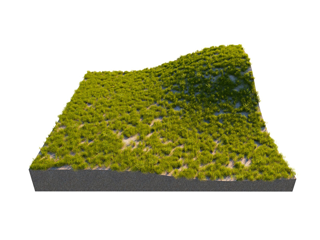
Random distribution
Random Distribution
Count – Defines an exact number of instances to scatter - either overall, or per area in the case of scattering defined by density (Per Square option). The number is always limited by the Instance Count Limit option. See the Count example below for more information.
Per Square – When enabled, the number of instances to scatter is defined by density (Count per square having the given edge length). The number of instances is always limited by the Instance Count Limit option. See the Per Square example below for more information.
Square Size – The specified value is the edge length of a square defining an area for computing the scatter density. The length is measured in world units.
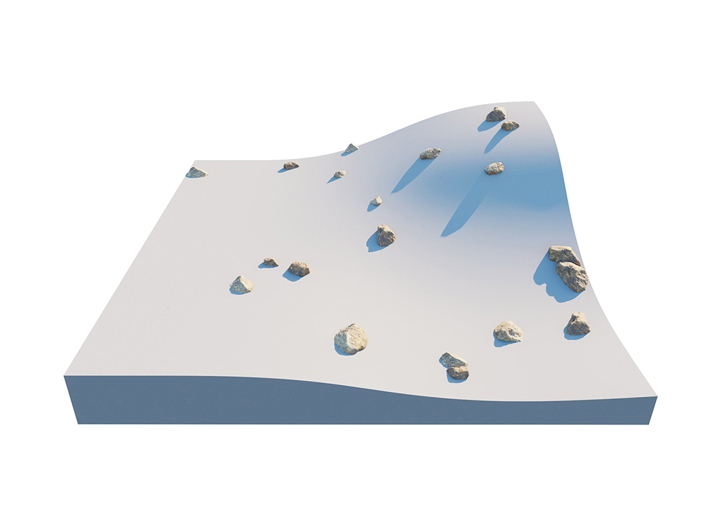
Density Texture – Allows a black-and-white texture map to be assigned. The map determines how the instances are scattered on the surface. User attributes can also be assigned to determine the scattering. See the Denisty example and the Density Texture example below for more information.

Example: Count
For this example, the Per square option is disabled.
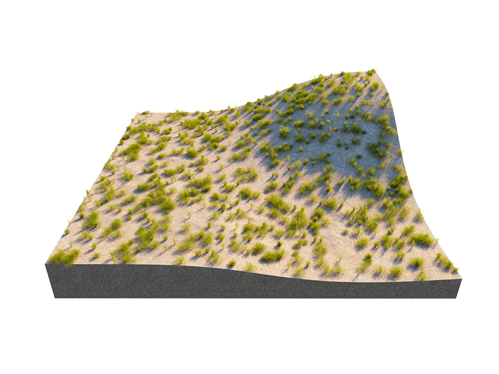
Count = 1000

Count = 2500

Count = 10000
Example: Per Square
For this example, the Per square option is enabled.
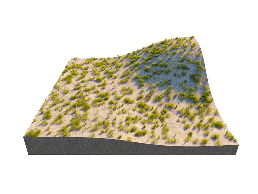
Count = 1000; Per Square = Off
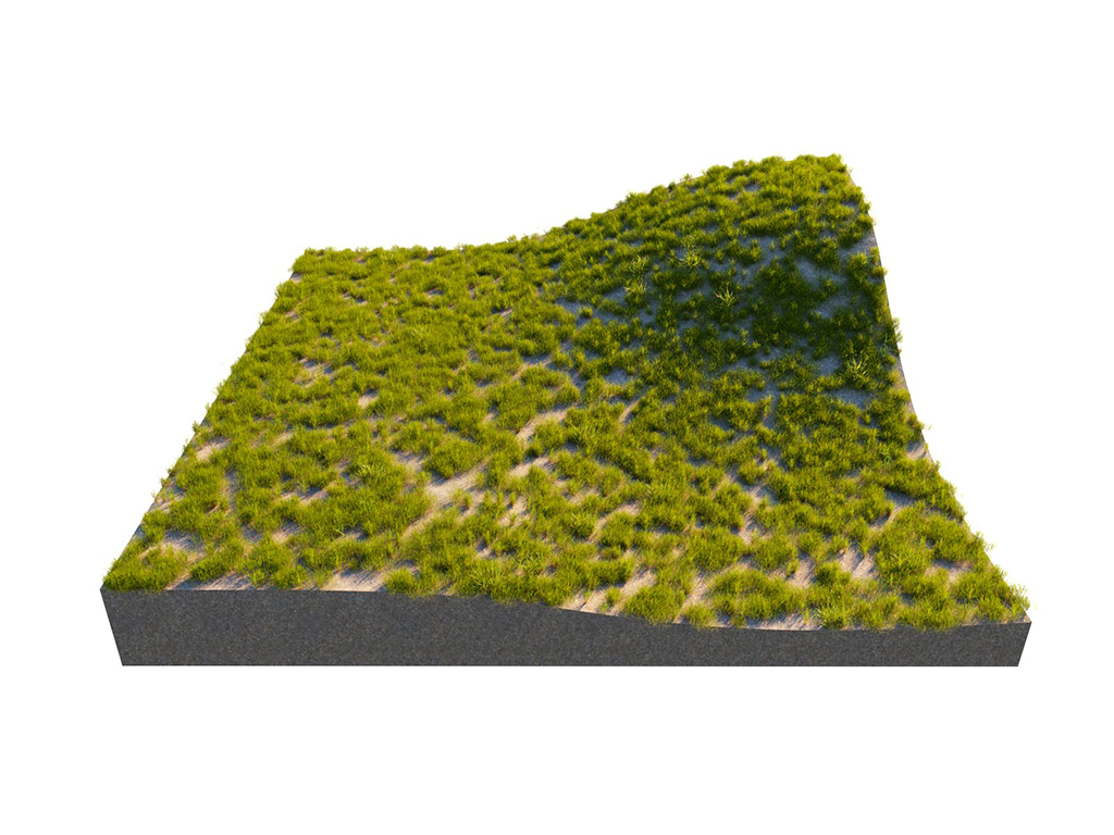
Count = 1000; Square Size = 1000
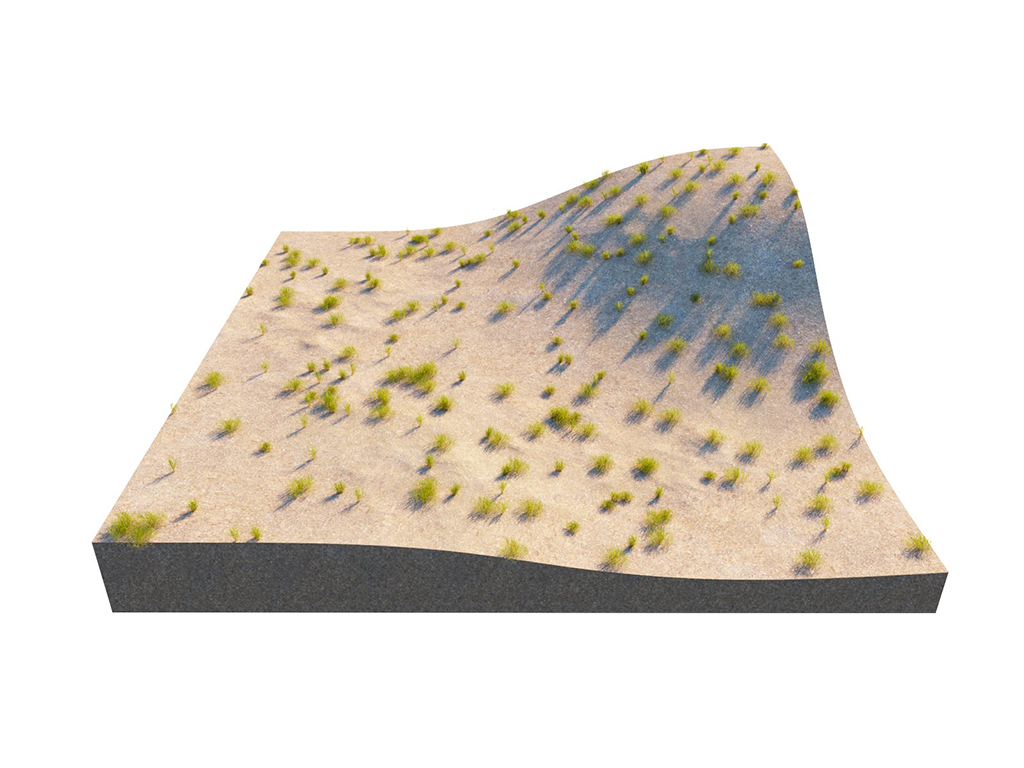
Count = 1000; Square Size = 4000
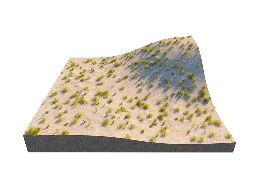
Count = 1; Square Size = 100

Count = 1; Square Size = 1000
Example: Density
The Square Size in this example is 500 cm. It shows how different maps create patterns of instances on the surface.

Count = 5000; Checker Map
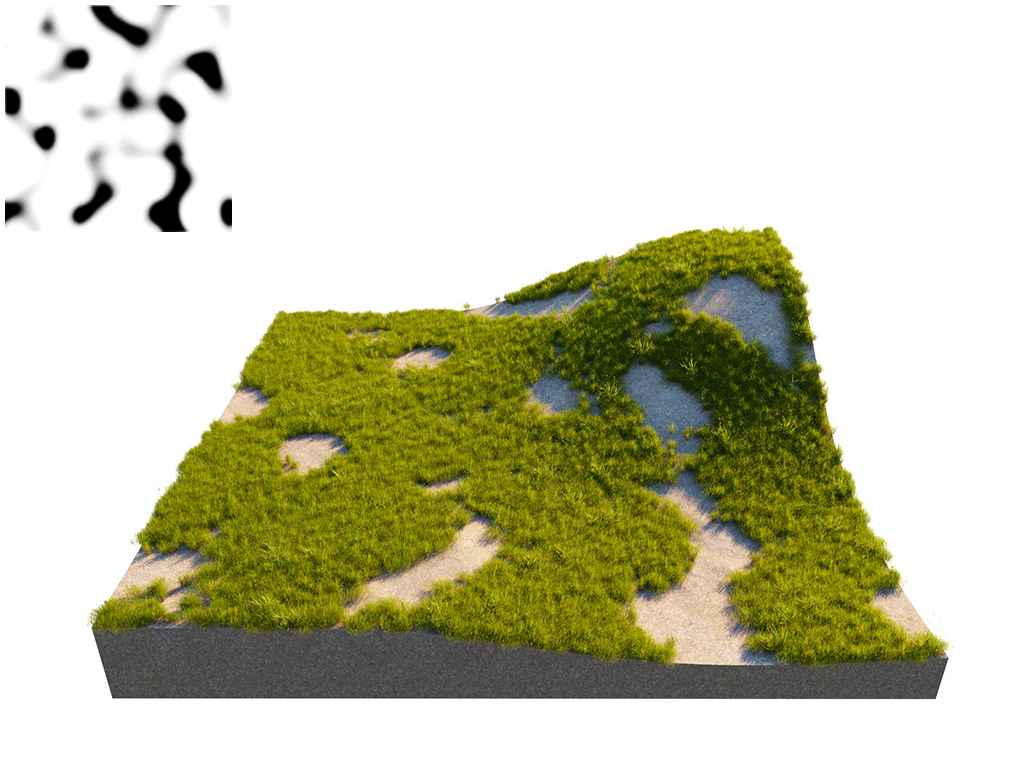
Count = 5000; Noise Map
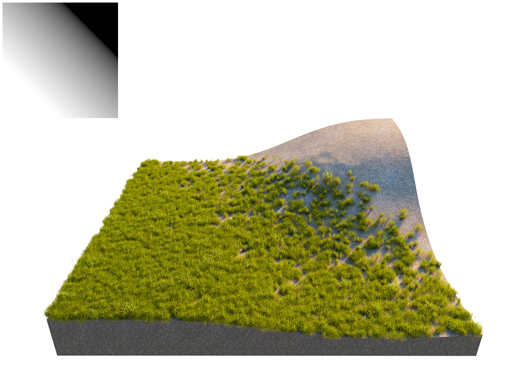
Count = 5000; Gradient Map
Example: Density Texture
Using a Density texture generates a brand new instance distribution. The total number of instances (approximate to the Count value) is preserved and distributed on all surfaces that correspond to map values above 0 (parts of the map not being purely black). Instances are more likely to be generated in areas with higher Density Texture values than darker ones.

On
Off
UV Map
Pattern – Determines a pattern for the scattering. See the Pattern example below for more information.
Grid – Rectangular grid.
Running Grid – Rectangular grid with every other row offset by half of the grid spacing.
Hexagonal Grid – Arranges instances into hexagons.
Lock V – When enabled, the values of the V coordinate for Spacing, Jitter and Offset are locked to the U coordinate's values. See the Offset examples below for more information.
Spacing – Scales the pattern in UV space. When Spacing is set to 1, the pattern occupies the whole space. When Spacing is set to 0.5, the pattern is repeated twice. See the Spacing example below for more information.
Jitter – Determines what percentage of the instances are randomly placed. When Jitter is set to 0, all instances are placed according to the UVW mapping. When Jitter is set to 1, all instances are randomly placed. See the Jitter example below for more information.
Offset – Offsets the pattern by the given value. Keep in mind that 0 and 1 Offset gives the same result, as 1 moves the pattern by one whole repetition. See the Offset examples below for more information.

Example: Pattern
This example shows the difference between the three Pattern options. The Spacing for all of them is set to 0.1.

Pattern = Grid

Pattern = Running Grid

Pattern = Hexagonal Grid
Example: Spacing
For this example, a Grid Pattern is used for all renders. The second set of images shows the Lock V option disabled and the U and V get different values.

Spacing = 0.1

Spacing = 0.25

Spacing = 0.5

Spacing = U 0.1; V 0.25

Spacing = U 0.1; V 0.5
Example: Jitter
In this example, the Pattern used is a rectangular Grid.

Jitter = 0

Jitter = 1

Jitter = 2
Example: Offset by Single Axis
For this example, the Pattern is set to Grid. Here, the offset is applied to the V axis only (the Lock V option is disabled).

Offset = U 0; V 0

Offset = U 0; V 0.5
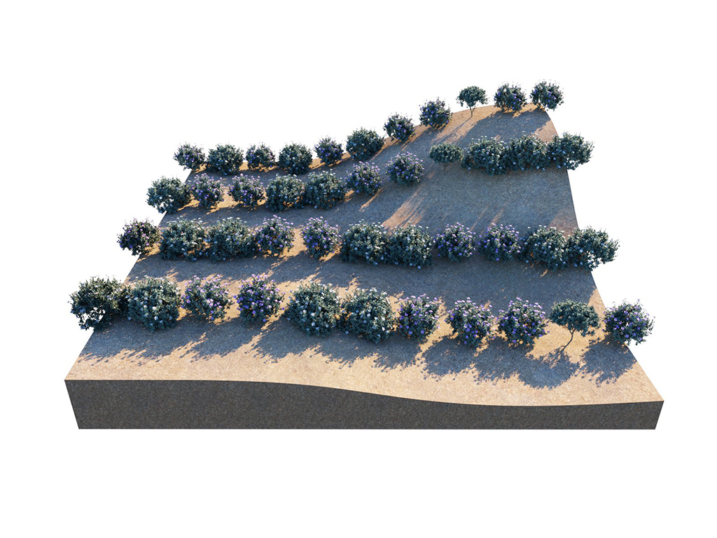
Offset = U 0; V 0.75

Offset = U 0; V 1
Example: Offset Locked V
For this example, the Pattern is set to a rectangular Grid. The offset here is applied to both the U and V axes (Lock V option is enabled).
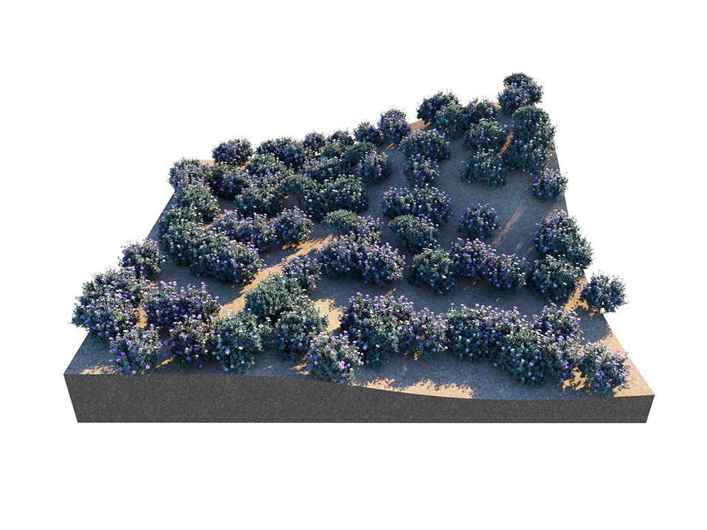
Offset = U 0; V 0

Offset = U 0.25; V 0.25
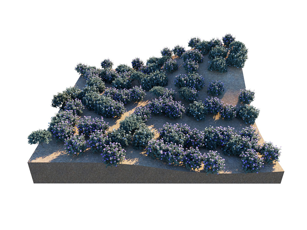
Offset = U 0.5; V 0.5

Offset = U 0.75; V 0.75

Offset = U 1; V 1
Notes
- Density Texture and maps added to Translation, Rotation, and Size are not represented in the viewport. For more information on texture interpolation, see the Texture Filter section.