V-Ray for Maya
Adding Displacement to Mixed Shaders
This tutorial shows how to add displacement to procedurally mixed shaders.
Last updated 19 September 2025
This tutorial shows how to add displacement to procedurally mixed shaders.
Overview
This workflow shows how we create a patchy grass material using the Mix mtlx node to combine two Standard Surface Shaders and, then, how we add and adjust displacement to enhance the look.
The scene used for the example contains a shader ball and studio lighting.
Download the scene to follow along

Steps
Initial Setup
- Firstly, go to the Windows menu and open the USD Layer Editor. Here, go to the Create menu and select Stage with New Layer. This creates a new USD layer in the scene, where we can copy our geometry.
- For this, right-click on the Shader_Ball group from the Outliner and select Duplicate as USD data > stageShape1. This creates a new USD stage in the scene. We can now hide (using Ctrl + H) the normal geometry group, so the shapes don't duplicate in the render.
- To assign a Standard Surface shader, select any of the USD shader ball elements, right-click on it and go to Assign New Material > MaterialX > Standard Surface. Then, to open the LookdevX editor, right-click on that same geometry again and select Show in LookdevX > New Tab... You can also Shift-select all of the shader ball elements and assign the material to all at once.
- In the LookdevX editor, you will see a standard_surface node. Double-click on it to go inside its structure. Here, we will start connecting our shaders with displacement.
Creating the Materials
Ground Material
The default standard_surface node we will use as the ground material. You can rename it, for easier navigation, if you like. In the screenshot, it's named Ground_Mtl.
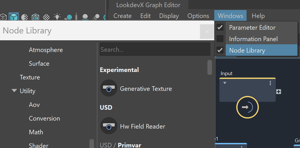
1. Create a Tiled Image node. You can access the node library quickly using the Tab keyboard key. Alternatively, you can open the node library as a separate window from the Windows menu in the LookdevX editor, where you need to enable the Node Library option. In the node library, you can browse through the categories or use the search field to find the Tiled Image mtlx node.
Click on the image to view it in full resolution.

2. In the File field of the Tiled Image node, click on the file icon ( ) and assign the ground_002_BaseColor.jpg file from the downloadable scene files. Then, connect the out + port of the tiled image node to the + base_color input of the ground shader.

3. Since we want this shader to be less reflective, set the Specular Color to RGB: 0.2, 0.2, 0.2. We will also map the reflections. Create another Tiled Image node by opening the node library options with the Tab key. In the File field, click on the file icon ( ) and assign the ground_002_Roughness.jpg file from the downloadable scene files. Open the out+ port and connect the g channel to the ground material's Specular > specular_roughness input.

Click on the image to view it in full resolution
Grass Material
We will go through a similar process for the grass material.
1. Create a new standard_surface node using the Tab key or from the Node Library window.
2. Create a Tiled Image node and in its File filed, assign the Grass_003_BaseColor.jpg file. Set its Uvtiling parameter to 2 on both axes. Connect the out+ port of the tiled image to the -base_color input of the new standard_surface shader.
3. Create a second Tiled Image node and attach the Grass_003_Roughness.jpg file to it. Set its Uvtiling parameter to 2 on both axes. Expand the out socket and connect the g output to the Specular > specular_roughness input. Set the Specular Color of the grass material to RGB: 0.4, 0.4, 0.4.
You can also rename the shader to Grass_Mtl and the textures to Grass_Diffuse and Grass_Roughness, respectively.

Making Compounds and Adding Displacement
1. Select the Ground_Mtl along with its connected textures and go to the Edit menu > Make Compound. A new compound node will appear in the editor instead of the selection. Rename it to something recognizable like Ground_Material. Now, when you double-click on the compound node, you will go one level down, and you can find the selection there. You can navigate between levels from the navigation bar at the top of the LookdevX viewport.

LookdevX navigation bar
2. Create a third Tiled Image node. In its File filed, connect the ground_002_Height.png file from the downloaded scene folder. Set its Node Type parameter to float. This will change the color and structure of the output port.
3. Then, create a Multiply (Math) mtlx node. Set its Node Type also to float. Connect the out port of the height texture to the in1 port of the Multiply node. Set the in2 value to 3. The Multiply node takes two values and multiplies them with each other. In this case, it multiplies all of the RGB values of the texture simultaneously, increasing or decreasing the intensity of the contrast, allowing us to fine-tune the displacement.

4. Connect the out port of the Multiply node to the empty port of the Output node ( ). It will automatically assume the type of the incoming connection. Rename the port (by right-clicking on it and selecting Rename Port) to Displacement. Connecting to the Output node allows that output to be used in the level above. If you go back to the standard_surface level, you will see that the Grass_Material compound has an out port and a Displacement port.

Output node context menu

This is how the final setup should look, with the added displacement.

Click on the image to view it in full resolution
The same setup is applied to the Grass_Mtl.
1. Firstly, select the whole material setup and go to Edit > Make Compound. Rename the compound to something like Grass_Material.
2. Create a new Tiled Image node. In its File filed, connect the Grass_003_Height.jpg file from the downloaded scene folder. Set its Node Type parameter to float. This will change the color and structure of the output port.
3. Then, create a Multiply (Math) mtlx node. Set its Node Type also to float. Connect the out port of the height texture to the in1 port of the Multiply node. Set the in2 value to 5.
4. Connect the out port of the Multiply node to the empty port of the Output node ( ). It will automatically assume the type of the incoming connection. Rename the port (by right-clicking on it and selecting Rename Port) to Displacement. Connecting to the Output node allows that output to be used in the level above. If you go back to the standard_surface level, you will see that the Grass_Material compound has an out port and a Displacement port.
Mixing
1. Create two Mix (Compound) mtlx nodes. Name one of them Displacement_mix. That will be the node used to mix the two displacement output values.
2. Set the Displacement_mix's Node Type to float. Set the normal mix node's Node Type to float/terminal.
3. Create a 3D Fractal Noise mtlx node. Set its Node Type to float. In the fractal properties, set the Amplitude to 10 controls the contrast between the lowest and the highest values, making the areas with grass and dirt more visible. Set the Octaves to 6, this will make the spots more rippled and interesting.
4. Connect the Grass_Material's out port to the fg (foreground) port of the mix1 node. Then, connect the Ground_Material's out port to the bg (background) port of the mix1 node.
Connect the out port of the fractal node to the mix input of the mix1 node. Connect the out port of the mix1 node to the mtlxsurface port of the Output node. This input port might be named surface, if in your case, no node is currently connected to it.
This applies the mixed materials to the surface of the linked geometries. Now, we need to add the displacement.
5. Connect the Grass_Material's Displacement port to the fg (foreground) port of the Displacement_mix node.
Connect the Ground_Material's Displacement port to the bg (background) port of the Displacement_mix node.
Connect the fractal node as the mix value for the Displacement_mix node.
6. Create a Displacement mtlx node. Connect the out port of the Displacement_mix to the displacement port of the newly-created node.
7. Connect the displacement node's out port to the displacement port of the Output node.
Now, the setup is complete! You can render to see the results. You can use the displacement node to control the strength of the displacement. In our case, we reduce the Scale parameter to 0.5 for a more subtle effect.
Feel free to play around with this scene and apply this workflow to your scenes.
This is the final render:
